
oday, military and avionics electronic systems are being developed with increased frequency ranges to add bandwidth and functionality while also being designed to fit smaller spaces. Meeting reduced size, weight, and power (SWaP) system goals poses challenges for high-frequency RF/microwave cables and connectors that must meet complex electrical, mechanical, and environmental specifications but also enable access to subsystem modules for maintenance and troubleshooting. Fortunately, new multiport interconnector technologies exhibit low loss at RF/microwave frequencies with high security and repeatability. Their straightforward approach makes it easy to disconnect even in space-limited applications while maintaining the most demanding EMI/EMC requirements.
Civilian and military avionics systems such as radar altimeters and microwave landing systems (MLS) that once occupied DC to 12 GHz are now expanding into higher frequencies, typically to 18 GHz and often as high as 40 GHz. This expansion requires subsystem interconnects capable of providing the highest, most reliable performance while also fitting within limited airframe space.
In general, military electronic systems such as electronic warfare (EW), radar, and electronic countermeasures (ECM) systems are being designed for smaller spaces and higher efficiency via modular architectures. Such design approaches require fool-proof wideband interconnections that can be connected and disconnected within the tightest spaces while meeting all the electrical, mechanical, and environmental requirements of traditionally more-permanent 50-Ω interconnections, including waveguide and coaxial cables and connectors. The limited space also increases the need for very low EM radiated and leakage levels at all high-frequency interconnections to minimize interference between subsystem modules.
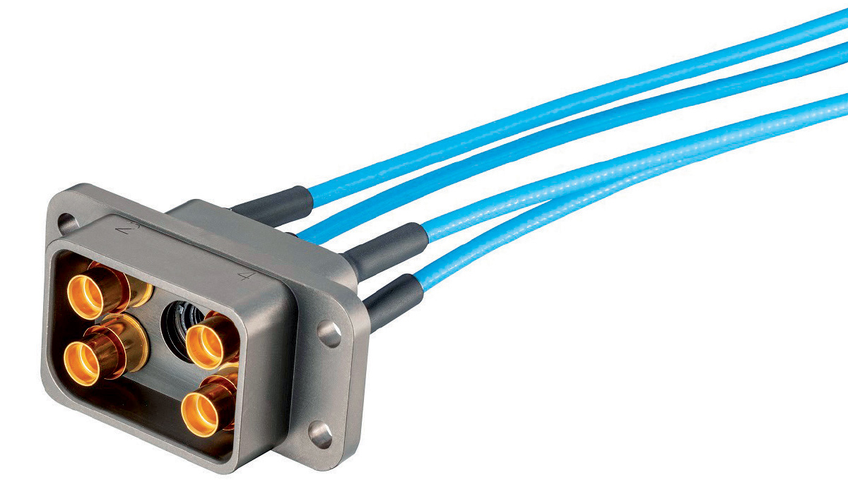
Applications with growing numbers of interconnections at increasing RF/microwave frequencies can easily evolve into tangled masses of coaxial cables with difficult-to-trace interconnections and terminations when each cable has its own input and output connectors. The basic concept of a multiport interconnection is to locate interconnection points for as many of the cables as possible within a single harness so that different subsystem modules can be interconnected at one junction point and even color-coded or labeled to ease identification and accessibility during maintenance and inspection.
But among the challenges in creating such a multiport harness is enabling straightforward connector-to-connector attachments within the harness without adding the equivalent size and weight of the total separate interconnections while maintaining the electrical and mechanical performance requirements
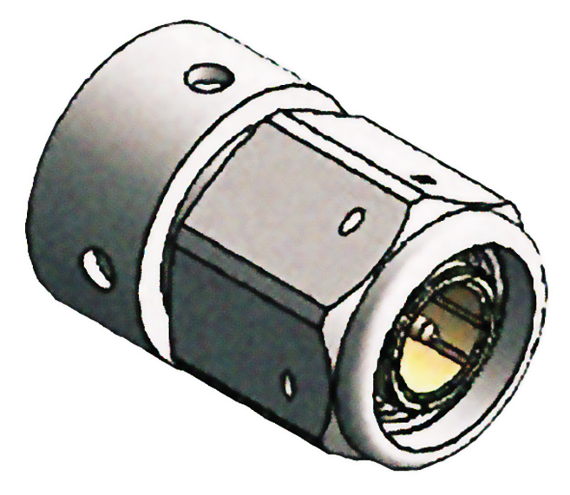
Traditional coaxial connectors such as 50-Ω Threaded Neill–Concelman (TNC) connectors (Figure 1) have long joined military and avionics subsystem modules at frequencies through 18 GHz, terminating flexible and semi-rigid coaxial cables by crimp or solder attachments. The threaded mating of male and female TNC connectors forms a secure and reliable electrical and mechanical connection capable of withstanding the high shock and vibration levels to which those systems are often subjected. A multiport connection must handle severe physical stress while reaching higher frequencies to support the wide bandwidths of modern systems. Since coaxial connectors are wavelength-dependent in terms of interface size, the interface dimensions must be much smaller than those of a traditional component such as a TNC connector to provide low-loss performance through 30 GHz or even 40 GHz.
As military and avionics systems designers target denser solutions for tighter spaces, they impose changing requirements for coaxial connectors and interfaces, not just regarding their size and weight but also the need for greater control of the electromagnetic (EM) energy passing through connector interfaces at higher frequencies.
A traditional military or avionic electronic system using multiple coaxial cable assemblies to link multiple subsystems and/or modules might have 50 or more individual connectors such as TNC connectors to join different subsystems to a main controller unit. Each connector occupies some amount of volume within the system equipment enclosure, the total volume of which can be reduced by an alternative connector interface such as a harness or shell with multiple ports that replace the comparable number of coaxial connectors that would normally be used for the interconnections.
The multiple-port interface is more complex than a single TNC interface but depending on the number of ports and the spacing between them, it can be made small enough to gain a significant advantage in size and weight compared to the same number of conventional coaxial cable assemblies. For military and avionics applications, such a multiport connector interface must meet or exceed the electrical, mechanical, and environmental specifications of the individual traditional coaxial connectors it is replacing.
A smaller multiport connector solution to replace multiple cable assemblies in a radar system may be required to provide amplitude matching between ports that is typically within tenths of a dB and a phase balance that is typically within a few degrees. Specifications for coaxial cables and other transmission lines used in electronic systems are usually generated by an OEM, who details all of the electrical and environmental requirements of their system and then works with an experienced RF assembly manufacturer who can design the optimized RF cable system. The ideal manufacturer is one who designs and manufactures the cable and connectors to create an optimized solution.
An effective multiport coaxial connector interface must also be designed to withstand the unique environmental conditions in which military and avionics systems are expected to operate, such as high shock and vibration, while maintaining electrically stable and secure interconnections. For systems that rely on signal amplitude and/or phase characteristics as part of a higher-order modulation scheme, effective multiport connector solutions must maintain continuous, undistorted electrical connections even under conditions of high shock, high vibration, and high humidity.
The deleterious effects of water absorption on a connector interface can be minimized by encasing the interface in a sealed enclosure. Cable assemblies for high-performance aircraft should be sealed to a level of not less than 1 x 10⁻⁵ cc/sec/ft of cable length. This lesson was learned in the 1970s when unsealed cable assemblies created reliability issues and resulted in the creation of Navy MIL-T-81490 and Air Force MIL-C-87104 specifications, which require 100% testing of vapor leakage, most often performed with a helium mass spectrometer.
Miniaturizing an RF/microwave connector interface requires tight spacing between multiple ports while still achieving sufficient isolation between ports to minimize EMI. For higher-power connector interfaces, port spacing can also play a role in the amount of heat that can be dissipated compared with conventional multiple coaxial cable assemblies. Conventional coaxial cable assemblies must tolerate wide operating temperature ranges as part of military and avionics systems without significant expansion or contraction of their conductive or dielectric materials. At higher RF/microwave frequencies, as signal wavelengths become smaller, the effects of physical changes in a material due to temperature are typically evidenced as variations in the amplitude and phase responses of signals carried by the channel’s connector interface.
As previously noted, signals used in modern military and avionics systems, including intelligence, radar, collision avoidance, electronic guidance, navigation, EW, and communications, are using higher frequencies and covering wider bandwidths. Military and avionics systems that once operated at frequencies of 18 GHz are now extending into the millimeter-wave (mmWave) frequency range of 40 GHz. Further, to increase functionality, these systems are increasing electronic density, with more circuits and devices per square inch than ever. With more antennas and sensors, high-density systems require a greater number of interconnections, with smaller interconnection dimensions to fit in tight spaces.
Densification and miniaturization are partially driven by the rising demands for small SWaP military and avionics systems which depend on tighter interconnection spacing. An effective multiport RF/microwave connector interface solution should support multiple coaxial cable diameters, including 0.047-, 0.087-, and 0.141-in./diameter flexible and semi-rigid cable types for flexibility around the world in different applications and different frequency ranges.

To accommodate densely packed, in-the-box applications, new high-performance, flexible cable assemblies are available for use that can be bent around tight corners and closely behind the connector to minimize footprint, save space, and simplify cable routing.
Depending on electrical and mechanical requirements, an extensive range of cables can also be used outside the LRU to connect to its end. Examples include military-grade, environmentally sealed cable assemblies most often used in airframe applications. These cables are available in a wide range of sizes, with armored options for use in applications where the cable will be subjected to a higher level of wear and tear and with lightweight options for applications where minimizing weight is critical. Selecting the best cable size will be based on the specific application’s operating frequency, loss, and power requirements.
It is also not uncommon to use multiple cable types in a series run to address installation challenges or achieve a desired electrical result, such as a specific attenuation value that may need to be matched to a different part of the aircraft. Multiport contacts can also be keyed to prevent mismating with the keying plug inserted into one of the ports to avoid mating to one with a different key arrangement. Keying can also be done by using shells that have different radii.