

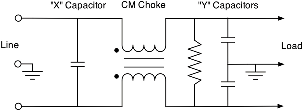
hen faced with excessive conducted emissions from switching power supplies, one of the first things to investigate is the adequacy of the power line filter. Line-powered switching supplies generally have both common mode (CM) and differential mode (DM) sections of the filter, as shown in the generalized schematic in Figure 1.
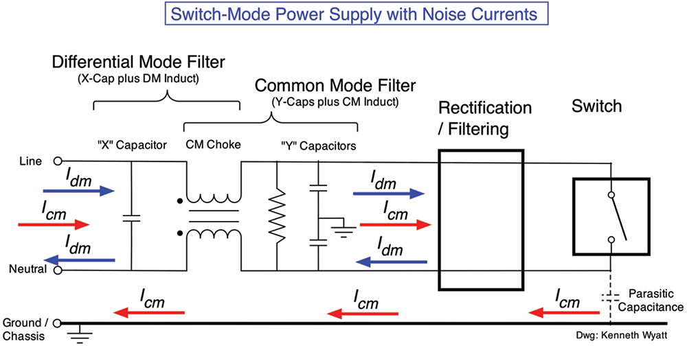

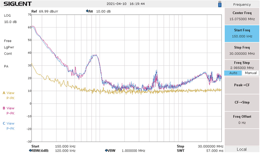
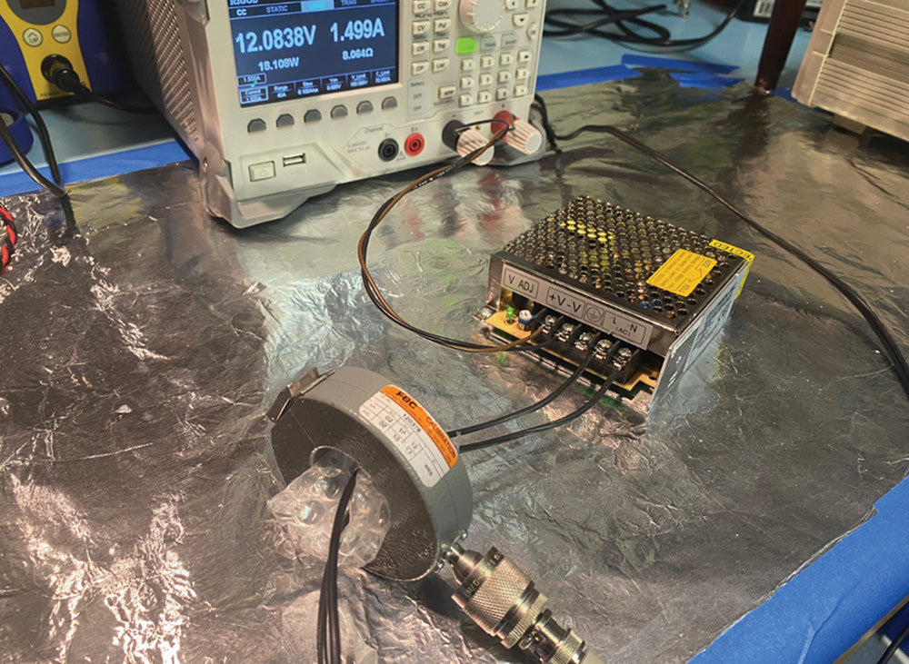
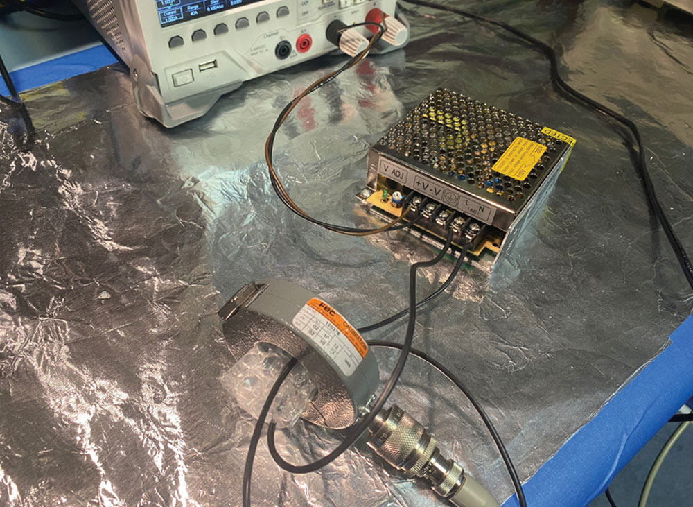
We’re all probably familiar with the procedure for measuring CM currents. We clamp the current probe around both line and neutral wires and make the measurement (Figure 5). Remember, CM currents flow out of both wires in the same direction and normally end up radiating out and conducting back into the mains. This is shown in the violet trace of Figure 7 (on page 12).

For example, a small series inductor on the line side would provide more impedance for the X-capacitor (CX) to work with. An alternative would be to increase the differential mode inductance of the common mode choke. Increasing CY will not likely be an option because this will increase the leakage current to the chassis, which could exceed the 3.5 mA maximum as dictated by product safety standards.
This technique of isolating the common mode and differential mode components of conducted noise currents may be a valuable tool for your troubleshooting toolbox.
By using the board below, I was able to select an “X” capacitor value that reduced the DM current (Figure 8).

- Tekbox Digital Solutions
- Kenneth Wyatt, Review: Tekbox LISNs, EDN, November 28, 2015.
- Mark Nave, Power Line Design for Switched-Mode Power Supplies, Springer, Second Edition, Springer, 2010.
- Arturo Mediano, “Review of the EMC Filters Kit from Würth Elektronik,” Interference Technology, 2018.