
EMC Concepts Explained
Shielding Effectiveness: The Impact of Loss Tangent on the Reflection and Absorption Losses
T

his article presents a concept of the loss tangent of the medium, which is often used to determine if a medium is a good conductor. A good conductor is defined as a medium in which the conduction current density is much greater than the displacement current density, or equivalently, the loss tangent of a medium (σ ⁄ ωε >> 1). The loss tangent of the medium is used to obtain an approximate solution for the shielding effectiveness in the far field, which in turn leads to the formulas for the shielding effectiveness in the near field [1].

Uniform Plane Wave Propagation in a Lossy Medium
To define the loss tangent of a medium, we begin with the uniform plane wave propagation in a lossy medium. The solution of the plane wave equations leads to the definition of the intrinsic impedance of the medium, which in turn leads to the concept of the loss tangent of the medium.

Consider a uniform plane wave propagating in a lossy medium, as shown in Figure 1.
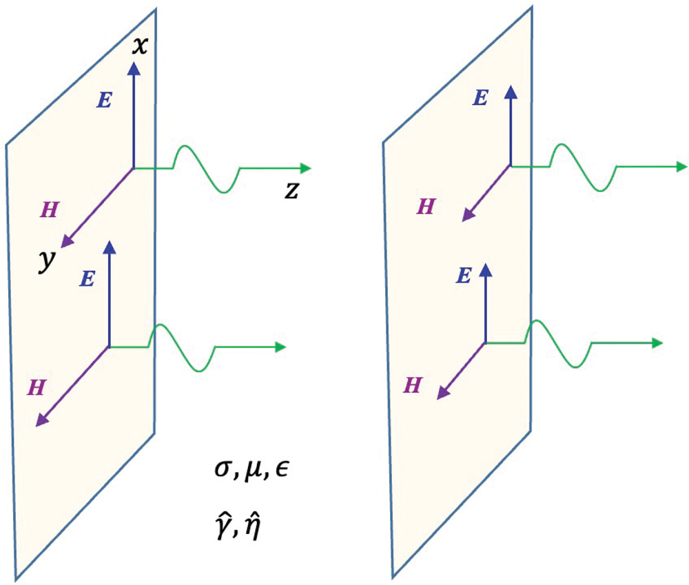
Figure 1: Uniform plane propagating in a lossy medium
The wave equations for sinusoidal variations are given by [2].
equation
equation
where
equation
is the propagation constant of the medium, where α is the attenuation constant and β is the phase constant.
The solutions of Eqs. (1.1) consist of forward and backward propagating waves, [2], and are given by
equation
equation
where
equation
is the intrinsic impedance of the medium.
Intrinsic Impedance of the Medium
Utilizing Eqs. (1.2) and (1.4) we get [1].
equation
thus,
equation
or
equation
and finally
equation
Note that Eq. (2.4) expresses the intrinsic impedance in terms of σ ⁄ ωε, which is termed loss tangent of the medium (a very important concept in shielding), and is the subject of the next section.
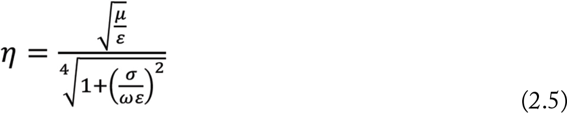
The magnitude of the intrinsic impedance is
equation
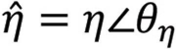
while the angle is
equation
It follows
equation
or
equation
showing that the angle of the intrinsic impedance is
equation
Loss Tangent of the Medium
Let’s start with Ampere’s Law (Maxwell’s equation) in a source-free medium, [1,2],
equation
or
equation
The first term on the right-hand side of Eq. (3.2) is the conduction current density
equation
while the second term is in displacement current density
equation
The conduction current represents an energy loss while the displacement current represents energy storage. The ratio of the magnitude of the conduction current density to that of the displacement current density is
equation
or
equation
where tan θ is known as the loss tangent and θ is the loss angle of the medium, as illustrated in Figure 2.

Loss tangent of the medium is a measure of the lossy nature of the material and provides a meaningful way of classifying different media, as shown in Figure 3.
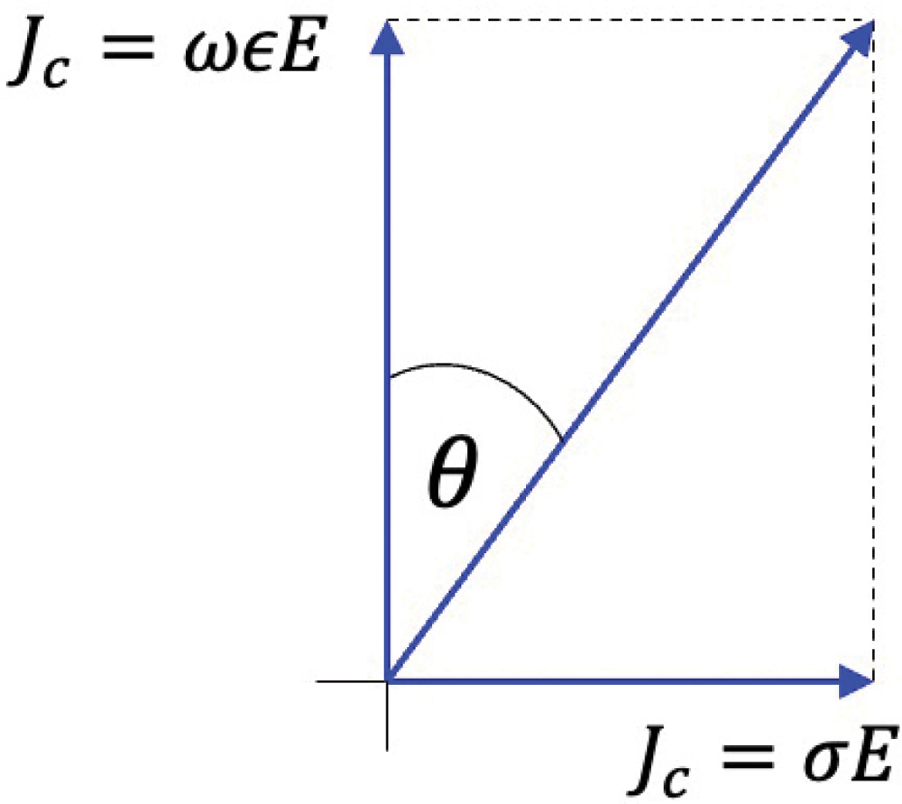
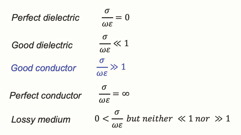
Figure 2: Loss angle of a medium
Figure 3: Loss tangent and classification of a medium
What does much larger (>>) or much smaller (<<) mean? Like many concepts in engineering, these two are not precisely defined. In mathematics, much larger or much smaller usually corresponds to the ratio of at least two orders of magnitude, i.e., the ratio of 100 or more. In engineering, this ratio often equals at least one order of magnitude, or 10.

Note that the loss tangent is a function of frequency and thus at one frequency a medium can be classified as a good conductor and at another frequency as a lossy medium or a good dielectric.

Calculations of the propagation constant and the intrinsic impedance can be simplified if the medium can be classified as a good conductor, as the following derivations show.

Recall, the propagation constant was defined by Eq. (1.2), repeated here

equation
which can be expressed in terms of the lost tangent of the medium as follows
equation
For good conductors we have
equation
And thus, the propagation constant in Eq. (3.8) can be approximated by
equation
The intrinsic impedance is related to the propagation constant by Eq. (2.2) as
equation
Utilizing the result in Eq. (3.10) in Eq. (3.11) we get
equation
In shielding, it is desirable to use good conductors as shields. Loss tangent of the medium is often used to compare different metallic shields at the frequency of interest.
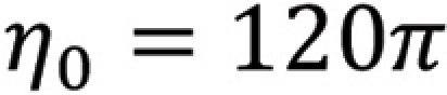
Another way of describing a metallic shield is by comparing its intrinsic impedance, , to that of free space, , as shown in the previous article [3]. Loss tangent and intrinsic impedance of the medium are related, as shown next.
From Eq. (2.9), we get
equation
Comparing it with Eq. (3.6) reveals that
equation
i.e., the loss angle is twice the angle of the intrinsic impedance.

Finally, let’s show the relationship between the loss tangent and the complex permittivity of the medium, often encountered when discussing dielectric media vs. conducting media.

From Eq. (3.1), we obtain

equation
or
equation
where the complex permittivity of the medium, , is
equation
or
equation
with the real part of it equal to
equation
and the imaginary part expressed by
equation
We observe that the ratio of ε″ to ε′ is the loss tangent of the medium, that is,
equation
For (non-conducting) dielectric medium the loss tangent is defined as
equation
while for a conductor the loss tangent is
equation
Loss Tangent and Far-Field/Near‑Field Shielding Formulas for Good Conductors
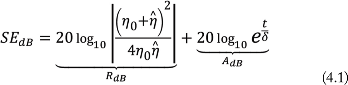
The shielding effectiveness, SE, of a thick (thickness of a shield is much greater than skin depth), conducting shield in the far field was derived in [1, 2], as
equation
where R is the reflection loss and A is the absorption loss, and δ is the skin depth. For good conductors, with the loss tangent
equation
the reflection loss and absorption loss in Eq. (4.1) can be approximated by [3]
equation
equation
where μr is the relative permeability, σr is the relative conductivity (with respect to copper), and t is the shield thickness in meters.
The far-field formula for the reflection loss in Eq. (4.3) is valid for both the electric and magnetic fields.

In the near field, the reflection loss for the electric field is [2,3]

equation
while the reflection loss for the magnetic field is
equation
The absorption loss for both fields is the same as in the far field.

In conclusion, let us emphasize that the far-field and near-field shielding effectiveness formulas were derived under the assumption of a good conductor, i.e., a conductor with the loss tangent satisfying the condition

equation
References
  1. Bogdan Adamczyk, Principles of Electromagnetic Compatibility – Laboratory Exercises and Lectures, Wiley, 2023.
  2. Clayton R. Paul, Introduction to Electromagnetic Compatibility, Wiley, 2006.
  3. Henry W. Ott, Electromagnetic Compatibility Engineering, Wiley, 2009

Share this story:
Dr. Bogdan Adamczyk
The Authors
Dr. Bogdan Adamczyk is professor and director of the EMC Center at Grand Valley State University (http://www.gvsu.edu/emccenter) where he performs EMC educational research and regularly teaches EM/EMC courses and EMC certificate courses for industry. He is an iNARTE-certified EMC Master Design Engineer. He is the author of two textbooks, “Foundations of Electromagnetic Compatibility with Practical Applications” (Wiley, 2017) and “Principles of Electromagnetic Compatibility: Laboratory Exercises and Lectures” (Wiley, 2024). He has been writing “EMC Concepts Explained” monthly since January 2017. He can be reached at adamczyb@gvsu.edu.
Dr. Peter Reiser
Since 2016, Dr. Peter Reiser has been a Professor at Heilbronn University of Applied Sciences, Germany, where he teaches automotive electronics and EMC. Before that, he spent 20 years working in the automotive industry as Manager of the EMC and quality laboratories, and 4 years in the shielding enclosures industry. He was also in charge of the EMC, thermal, and mechanical simulations teams. He can be reached at peter.reiser@hs-heilbronn.de.
Scott Mee
Scott Mee is a co-founder and owner at E3 Compliance, which specializes in EMC & SIPI design, simulation, pre-compliance testing, and diagnostics. He has published and presented numerous articles and papers on EMC. He is an iNARTE certified EMC Engineer and Master EMC Design Engineer. Mee participates in the industrial collaboration with GVSU at the EMC Center. He can be reached at scott.mee@e3compliance.com.