Four Useful Tips for Using Affordable Benchtop Spectrum Analyzers
ver the past few years, several equipment manufacturers have launched affordable benchtop spectrum analyzers that are useful for several aspects of EMI troubleshooting and pre-compliance work. These units are often priced between $1000 and $3000 (USD), depending on the frequency range and model types. In addition, some models include a few paid add-on options, such as a tracking generator, EMI filter, reflection loss bridge, etc. Among these options, the tracking generator and EMI filter are worth having if you do pre-compliance EMI work.
Wyatt has many blog articles on this subject including [1], and his “EMC Troubleshooting Trilogy” presents guidelines for selecting a spectrum analyzer. Another useful resource is Mayerhofer’s “How to correctly use spectrum analyzers for EMC pre-compliance tests” [3]. Engineers can check out these articles (including the manufacturers’ application notes) to familiarize themselves with a spectrum analyzer’s basic and advanced functions.
In this column, we discuss several important features of a spectrum analyzer not covered in previous articles that are worth your consideration.
- When performing an EMI scan, the spectrum analyzer is connected to the LISN when the unit is turned on and off. This can be a problem because an inductive load’s “kickback” voltage could introduce a significantly high level of transient voltage that may potentially damage the RF front of a spectrum analyzer. This also applies when the spectrum analyzer is connected to an RF current probe clamped on a motor winding.
- The EMI spectrum analyzer is used to measure conducted emissions from 150 kHz. Engineers notice the “ADC overload” measurement error during the measurement, but the measured signals often seem to be within the limit. This is most likely due to the high spurious levels of noise at relatively low frequencies. If the analyzer is left on during the measurement, there is a risk of damaging the analyzer.
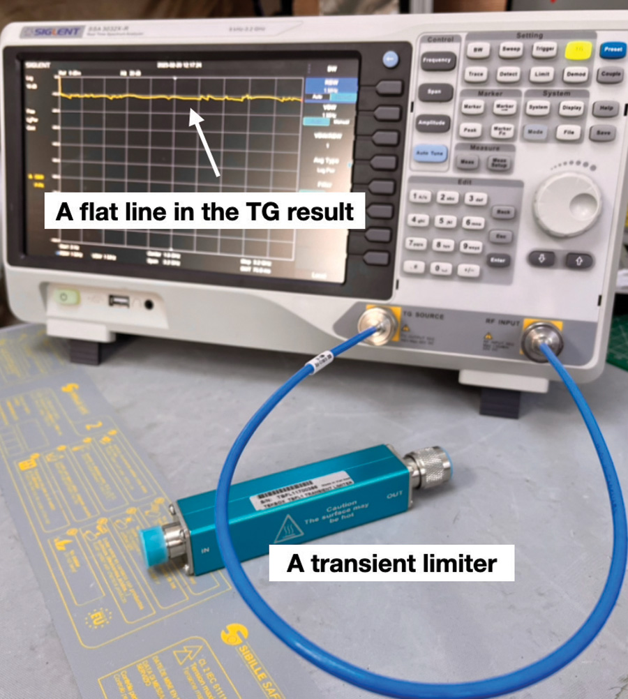
Therefore, a quick pre-check of the spectrum analyzer is necessary. The procedure is simple and quick to perform. There are two ways of performing a pre‑check.
- If the spectrum analyzer has enabled the tracking generator (TG) function, simply connect the TG output and the spectrum input using a coaxial cable and perform a TG scan. One should see a flat, straight line across the whole frequency range at the supplied TG power level (often between -20 dBm and 0 dBm). This is shown in Figure 1.
- If the spectrum analyzer does not feature the TG function, simply connect a function generator/signal generator to test a few selected frequency points. This requires a high-performance generator (to ensure the output waveform is sinusoidal).
- Transient limiters and high-pass filters can introduce measurement errors and should be used cautiously [4].
- External attenuators do not have diode clipping issues, but they raise the spectrum analyzer’s noise floor, reducing the system’s sensitivity.
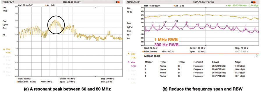
A typical case involves a radiated emission test, in which a resonance peak is observed in the frequency range of 60 and 80MHz in the plot of 30 – 300 MHz. To find the noise source that resonates at this frequency range, we can reduce the measurement range to this narrow frequency region and reduce the resolution bandwidth (RBW), as shown in Figure 2. In this case, a switching frequency of 1.8 MHz was observed, which pointed to a switched-mode power supply on the board under test.
Engineers should always be aware that spectrum analyzers produce RF noise. The mains cable of the spectrum analyzer conducts and radiates RF noise in the frequency range of 1 MHz and 300 MHz.
There are effective ways of reducing ambient noise, which we’ll discuss in detail in our next “Troubleshooting” column. But, in brief, engineers should always be aware that spectrum analyzers produce RF noise. The mains cable of the spectrum analyzer conducts and radiates RF noise in the frequency range of 1 MHz and 300 MHz. This can be measured by connecting an RF current probe on the mains cable.
Engineers who perform the test should differentiate the noise from the DUT and the test equipment used. In one case, when the author was testing a motor drive cable noise, the RF noise from the spectrum analyzer was coupled to the motor cable being measured, which led to misleading information.
- K. Wyatt, “Choosing an Affordable Spectrum Analyzer,” SIJ, 25 May 2022. https://www.signalintegrityjournal.com/blogs/17-practical-emc/post/2613-choosing-an-affordable-spectrum-analyzer
- K. Wyatt, “EMC Troubleshooting Trilogy.” https://www.amazon.com/gp/product/B0B4KB8YJS.
- M. Mayerhofer, “How to correctly use spectrum analyzers for EMC pre-compliance tests.” https://www.tekbox.com/product/AN_spectrum_analyzers_for_EMC_testing.pdf
- T. Williams, “Measurement Error Caused by the Transient Limiter.” http://www.elmac.co.uk/EMC_Zurich_limiter-hazard.pdf

Dr. Min Zhang is the founder and principal EMC consultant of Mach One Design Ltd, a UK-based engineering firm that specializes in EMC consulting, troubleshooting, and training. His in-depth knowledge in power electronics, digital electronics, electric machines, and product design has benefitted companies worldwide. Zhang can be reached at info@mach1desgin.co.uk.