expect the title of this article might raise a few eyebrows! It is very common for people doing simulations to make a measurement of a similar set up to validate the simulation. This is a reasonable precaution since modern simulation tools will give a very accurate answer to whatever question it is asked. The real issue is did the tool user understand the problem well enough to capture the important features, and did the user understand the tool well enough to use it correctly.
However, we usually do not expect a measurement to be validated. After all, measurements are a great emotional comfort! I have seen many test laboratories claim measurement uncertainty in the 1.5 to 2 dB range. However, whenever I ask an experienced EMC test person how well they might expect to correlate between two different laboratories, I often get a response that anything better than 8 dB is ok, and certainly, I have never been told that better than 6 dB is expected! This tells me what the ”real” laboratory accuracy is. And this is when all the equipment is functioning to specification.
When we look at a typical EMC chamber, we all know and accept that the chamber effects can be +/- 4 dB from the theoretical. This alone could account for 6 dB or more difference between laboratories! When we add the difference between different antenna’s response to the nearness of the metal chamber floor as it travels up/down the antenna mast (which can be as much as 4 dB), the potential for site-to-site variation continues to climb. Then we have an antenna factor that was probably measured in a different test environment than where we use it, cable loss, receiver accuracy, etc. So maybe when a simulation is not validated in the test laboratory, we should simply try another test laboratory? (I am NOT recommending this practice! But I think you see my point.)
Obviously it would be cost prohibitive to improve all the things in the previous paragraph so the site-to-site repeatability is reduced to 1-2 dB. However, I do think we should be careful to understand exactly how accurate the measurements are and not place too much credibility in the numbers resulting from such measurements.
Again, all the above assumes the equipment is operating correctly. I recently heard a story where a salesman was demonstrating a comb generator source to a potential customer in their chamber. The receiver measured fine over a portion of the total frequency range. However, there was one band where there were no comb harmonics! It turned out that the receiver had a broken band, and the operators were not aware of it and had been using the receiver with the broken band on product measurements for a while. I have also heard many stories of how a cable from the antenna had a broken connector without operators realizing it. This points to the importance of having (and using) a test artifact on a regular basis.
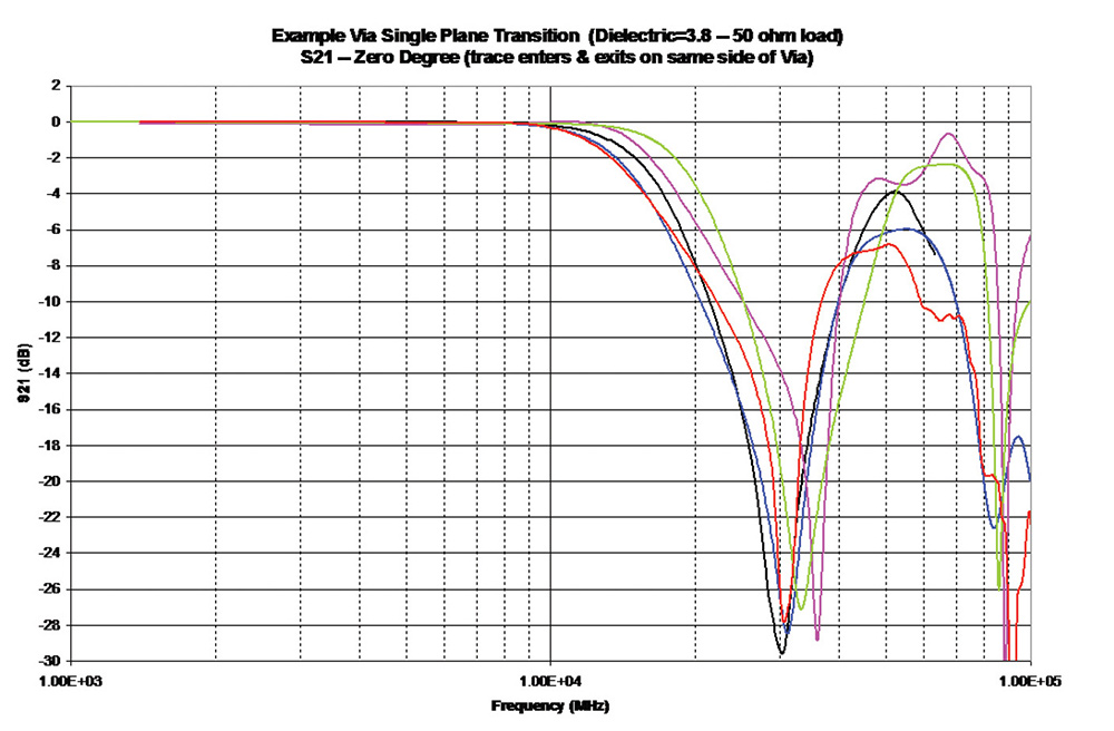
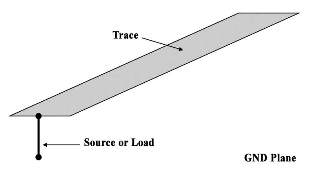
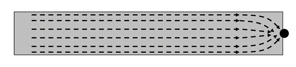
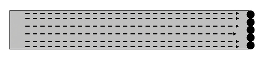
Usually, benchtop measurements are better controlled with fewer chances for error (although the examples above could also happen in a benchtop setting). However, these measurements often introduce other, more subtle issues. Many years ago, I wanted to make measurements of the impedance between power and ground-reference planes on a printed circuit board (PCB) in order to validate some simulations of the same PCB. The measurements were very different than the simulation results, and this was because the measurement VNA had 50-ohm ports. I had not loaded my simulation ports with 50 ohms. (Why would anyone ever put 50 ohms between power and ground reference?). Once I modified the simulation to include the loading, the simulation and measurements agreed very well. This was a clear example where the measurement changed the thing I was trying to measure!
Of course, the story is not completely one-sided. Simulations can have subtle issues that can cause errors. Years ago, I was involved in a project at IBM where we wanted to know the impedance of vias transitioning through 250 mil thick PCB up to 50-60 GHz. Test equipment, probing techniques, and de-embedding probe effects were not as advanced as they are now. So a group of five engineers teamed up to do simulations on the via structure using five different simulation techniques since it is commonly accepted that if very different simulation techniques give the same result, it is likely the correct result.
Some careful analysis discovered that the various techniques/engineers all made assumptions about the geometry that made sense to them individually but were slightly different from each of the others. First, it is important to understand that no simulation technique uses round objects, even if the software tool displays a round object. The round object must be converted to rectangular or triangular objects in order for the solution software to properly grid the object. Users should always check the gridding to see that this conversion has been done correctly.
In the above instance, one of the engineers converted the round via, via pad, and via keep out to a square that would fit inside the round object. Another converted the round to a square where the round fit inside the square. Another engineer made the area of the round the same as the area of the square. Once these differences were understood, and the models modified so that all were using the same dimensions, then the simulations all agreed very well. The main point is that each engineer, being very experienced in modeling/simulation, made assumptions that seemed reasonable. The tools gave very accurate answers to the models, but the models were not 100 percent correct!


On the other hand, simulations will usually not change the thing they are try to measure, but subtle issues can creep in the model, yielding incorrect results. These simulation tools are extremely powerful, and should be a tool in the engineer’s tool box, but they cannot be used as simply as a screwdriver! Training on the simulation technique to understand its strength and its weaknesses is vital.
The bottom line? Question everything.