


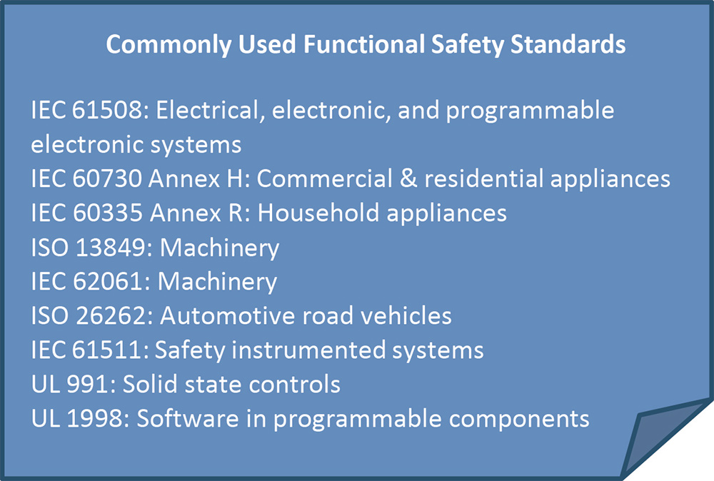
unctional safety (FS) is a complex, and oftentimes a confusing, subject even for those familiar with product safety and certification. With good reason, there are numerous functional safety standards that apply to various product types and applications, each with their own nuanced requirements. Some end-product standards specify one or more FS standards to use for embedded controls, while others leave it open to interpretation.
In short, FS evaluations are required whenever a control—regardless of whether it is electronic, pneumatic, hydraulic, or another type—is used to achieve safe operation of a product. Depending on the application specifics and the end-product standard, functional safety may only encompass hardware controls or include both hardware and software.
Some simple examples include thermal limiting controls on a heater, pressure limit controls on an air compressor, or interlock sensors that disconnect a machine when a door is opened. More complex examples include safety stops of machinery, collision detection systems for collaborative robots (“cobots”), sensing systems to prevent a robotic vacuum cleaner from falling down a flight of stairs, or the object detection/avoidance systems of autonomous vehicles.
While these examples represent a wide range of complexity and refer to different FS standards for evaluation, the good news is that the core functional safety process is similar for almost all projects.
This article will examine the process flow for an FS evaluation and provide an overview of each major step. Although it would take multiple books to go through every step of FS in detail, the expectation is that the following details will provide an understanding of the basic process.
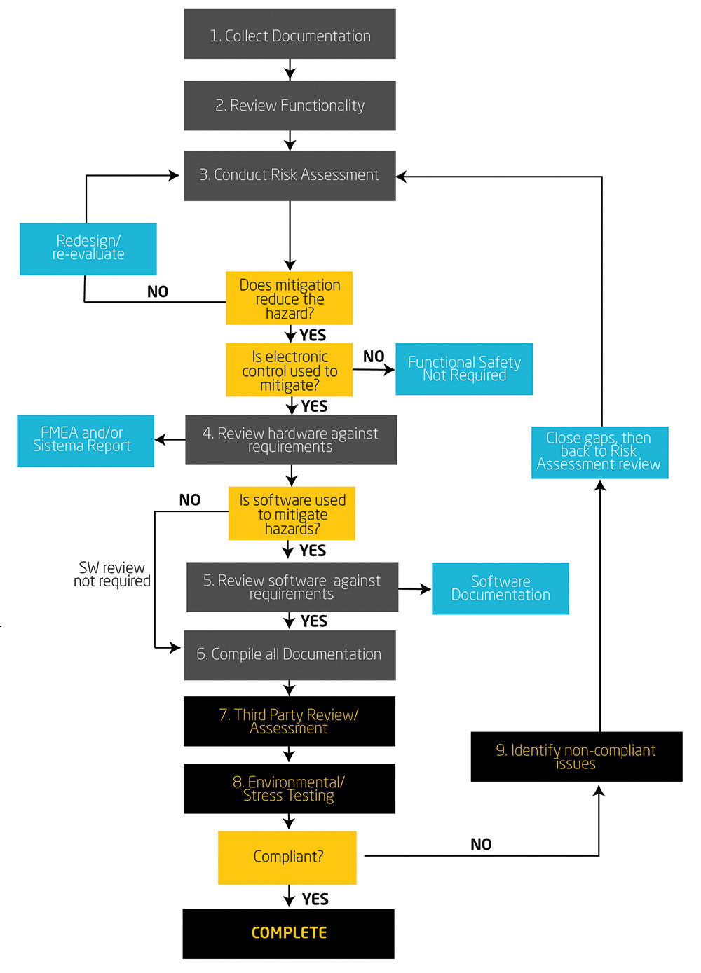
Steps 1 through 6 may be conducted by the system designer, system integrator, safety engineer, or others appropriately qualified on the product development side. If seeking third-party certification, steps 7-9 may be conducted by a third-party safety evaluator or similar service providing independent product certification. Clients who are self-declaring may choose to do this as part of their own internal review.
This FS process may be part of a larger product safety evaluation, or it may be a stand-alone FS evaluation, depending on the product and its specific application. In an ideal scenario, these steps would be conducted as part of the design concept phase before the first circuit is drawn or any lines of code are written. Often, these steps occur after a product has been developed or even after the product is already on the market. The benefits are significant when the FS process is considered sooner, meaning a proactive approach yields lower overall time to market and development costs versus taking more of a reactive approach to fixing issues at the end.
The first three steps are intended to compile all relevant information, construct a risk assessment with a ranking of hazards, and identify controls mitigating the hazards. In the subsequent steps, the control systems are identified and evaluated to show they meet the required level of protection necessary for the hazards involved. Any safety critical software (including firmware) aspects of the design need to be properly documented as well. A review of the complete documentation package, plus any required environmental testing (EMC immunity, thermal cycling, etc.), will be conducted to help ensure continuing safe operation per the specific FS standard.
Once the hazards are identified, they are ranked based on the severity of injury, the frequency of exposure, and the likelihood of occurrence. Some standards and products also include risks of property damage. These ratings will identify which hazards present an unacceptable level of risk and where mitigation means are required.
Any mitigation means should be identified and referenced, along with a notation of whether any of these mitigation means include functional safety aspects. For example, mechanical guarding of a hazard would not be considered an FS mitigation, while providing a light curtain to guard against the same hazard would be considered FS. This is because a stationary mechanical guard does not depend on an electronic, hydraulic, or pneumatic control to provide its safety function, whereas the light curtain depends on sensors and control logic to provide this safety function.
This activity in the RA will also identify if additional risk reduction measures are required to bring the total hazard down to an acceptable level. Hazard levels, acceptable risk, and other aspects of the RA will vary from product to product as influenced by the application. Some references on best practices for conducting an RA are the standards ISO 12100 – Safety of Machinery – General Principles for Design – Risk Assessment and Risk Reduction, or ANSI B11.0 – Safety of Machinery.
The rating of the hazards will directly correlate to the safety level requirements of the FS controls. This should make intuitive sense, as a hazard that will cause a scrape or cut is much different than one that will cause death or permanent injury. It is important to note that the acceptability of injury varies among different products and their intended use. FS controls that mitigate more severe hazards generally need to be designed with higher reliability, and the FS standards may impose other, more stringent requirements on such controls. This will be illustrated through an example in Step 4 below.
In summary, the output of the RA will include the identification of:
- Hazards and risk rankings
- Mitigation means
- Functional safety controls
- Required performance levels for the FS controls
- If no, redesign and re-evaluate
- If yes, then the next decision tree is used to determine if electronic controls are used (i.e., FS controls)
Let’s consider an example: evaluating a product to ISO 13849 (Safety of Machinery).
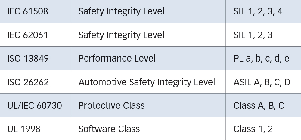
From the chart in Table 1, we know this standard uses PLa through PLe ratings for the performance level of controls. A rating of PLa applies to controls mitigating low-risk hazards, up to a rating of PLe for controls mitigating the most severe hazard risks. If the system uses a control where the calculation made during the risk assessment results in a low level of hazard mitigation—say PLa—then it may be acceptable to use a single-channel circuit architecture with lower reliability components. But, if the hazard is more severe, such as shown in Figure 2, a PLd or PLe level of safety will be required. For these higher performance levels, this particular standard will require redundancy, diagnostic coverage, and reduction of common cause failure modes as defined in the standard.
In this instance, the FS control used (as noted in the “Risk reduction measure taken” column) is an interlock that will mitigate the “medium” level hazard based on this particular RA ranking. The required PL for this hazard is calculated as “PLd,” as shown here. The standard ISO 13849 includes the methodology for this calculation based on S, F, and P (Severity [shown as DPH in Figure 2], Frequency of Exposure, and Possibility of Avoidance). The FS control used is an interlock that will mitigate the “medium” level hazard based on this particular RA ranking.
The rating of each hazard would typically be done as part of the risk assessment, so that during this step the primary task is to review the hardware design to verify it meets the requirements necessary for its performance. The evaluation of hardware may be done by referring to manufacturer reliability data for off‑the-shelf components, conducting failure mode and effect analysis (FMEA) of custom-built components, conducting a SISTEMA review (SISTEMA is a software tool for the application of ISO 13849), or by using other acceptable, industry-recognized methodologies.
The output from this step is documentation showing that the hardware effectively provides the required level of performance for each of the hazards identified.

In general, the requirements for FS software are based on effective practices in coding, error checking, process documentation, version control, and methods for validation and verification (V&V) at various stages of the development lifecycle. The product development lifecycle V-model is often referenced here to ensure that appropriate V&V for software is conducted at each stage of the design process. Some standards also include requirements for coding techniques, such as defensive coding practices.
The output of this step will be a set of documents showing compliance with the software development process.

One of the most important takeaways from this activity is to provide traceability: the documentation should provide supporting evidence and a clear rationale for the decisions made.
For example, if a machine presents a risk of injury due to high sound levels, the RA should cite the sound level measurement requirement (such as an OSHA requirement), the measurement made, and any other supporting information that provides a clear understanding of the assessment performed.
As mentioned earlier, functional safety also generally requires operational, thermal, and environmental testing—often specific testing for electromagnetic compatibility (EMC), including impulse and immunity testing. This testing would be conducted at this point in the evaluation.
If no non-compliances are determined, barring further compliance issues, then the FS evaluation is considered complete.
- Failure mode and effects analysis (FMEA)—A methodology to identify possible failures in a design, typically applied to hardware to analyze safe or unsafe failures when faults are injected.
- Hazard—Potential source of harm to persons, property, or the environment. A hazard can be qualified in order to define its origin (e.g., mechanical hazard, electrical hazard) or the nature of the potential harm (e.g., electric shock hazard, cutting hazard, toxic hazard, fire hazard). (ISO 13849-1:2015, 3.1.11)
- Layers of protection analysis (LOPA)—A methodology for assessing adequacy of protection layers used to mitigate a risk. Includes evaluation of the frequency of potential incidents and the probability of failure of protection layers. Typically used in the process industry. (Handbook of Fire and Explosion Protection, Dennis P. Nolan, 2019).
- Required performance level (PLr)—The performance level required in order to achieve the required risk reduction for a safety function. (ISO 13849-1:2015, 3.1.24)
- Risk—Combination of the probability of occurrence of harm and the severity of that harm. (ISO 12100:2010, 3.12)
- Risk assessment—Overall process comprising risk analysis and risk evaluation (ISO 12100:2010, 3.17). This is a methodology for identifying the risks and hazards of a product or process, the severity of the hazards, any mitigation methods, and may include scoring of functional safety control requirements.
- Safety function—The function of the machine whose failure can result in an immediate increase of the risk(s). (ISO 12100:2010, 3.30)
- Safety integrity level (SIL)—Discrete level (one out of a possible four) for specifying the safety requirements of functions in a safety-related system. SIL 4 has the highest level of safety integrity and SIL 1 has the lowest. (IEC 61508‑4:1998, 3.5.6)
- Safety-related part of a control system (SRP/CS)—The combined safety-related parts of a control system start at the point where the safety-related input signals are initiated (including, for example, the actuating cam and the roller of the position switch) and end at the output of the power control elements (including, for example, the main contacts of a contactor). Also known as an SRCS. (ISO 13849-1:2015, 3.1.1)