Assessing Safety and Performance of LED “Grow Lights”
Accessing the Growing Market for
Drones in the U.S.
EMC and Safety for Installations: Part 2
Developments in Ground Bonding Networks
Assessing Safety and Performance of LED “Grow Lights”
Accessing the Growing Market for
Drones in the U.S.
EMC and Safety for Installations: Part 2
Developments in Ground Bonding Networks

ISSN 1948-8254 (print)
ISSN 1948-8262 (online)
is published by
Same Page Publishing Inc.
451 King Street, #458
Littleton, MA 01460-1279
tel: (978) 486-4684
fax: (978) 486-4691
©Copyright 2020 Same Page Publishing, Inc. all rights reserved
Contents may not be reproduced in any form without the prior consent of the publisher.
While every attempt is made to provide accurate information, neither the publisher nor the authors accept any liability for errors or omissions.
publisher
bruce@brucearch.com
keith.armstrong@
cherryclough.com
Leo@EisnerSafety.com
dgerke@emiguru.com
ken.javor@emcompliance.com
kenrossesq@gmail.com
wernerschaefer@comcast.net
Subscriptions outside North America are $129 for 12 issues. The digital edition is free.
Please contact our circulation department at circulation@incompliancemag.com
The Commission’s Report and Order and Further Notice of Proposed Rulemaking lays the groundwork for making 100 megahertz of spectrum in the 3.45-3.55 GHz band available for 5G use. Specifically, the Report and Order adopts a 2019 FCC proposal to remove secondary, non-federal allocations from the 3.3-3.55 GHz band as a first step to facilitate spectrum sharing between federal incumbents and commercial operations.
- “The Accreditation Scheme for Conformity Assessment (ASCA) Pilot Program”—This guidance describes how the Pilot accreditation program was designed and how accreditation bodies, testing laboratories and device manufacturers can participate in the program.
- “Basic Safety and Essential Performance of Medical Electrical Equipment, Medical Electrical Systems, and Laboratory Medical Equipment – Standards Specific Information for the Accreditation Scheme for Conformity Assessment (ASCA) Pilot Program”—This guidance provides information specific to the basic safety and essential performance of standards in the Pilot program. Specifically, the guidance addresses which standards are eligible for inclusion in the Pilot, ASCA program specifications for those standards, and recommended premarket submission contents specific to those standards when testing is conducted by an ASCA-accredited testing laboratory.

n [1] the return path of high-frequency current was discussed for a two-layer PCB configuration shown in Figure 1a.
It was shown that at high frequencies the return current takes the path of least inductance, which is directly underneath the top trace, because this represents the smallest loop area (smallest impedance). This is shown in Figure 1b.
This article discusses the distribution of a PCB return current underneath top trace for the microstrip configuration. Next month’s article will discuss the distribution for the stripline configurations.
Figure 3 shows a single trace on a signal layer carrying a forward current and the associated fields.
This article is a follow-up to “What’s the trouble with AMRs?” In Compliance Magazine, January 2020.
he purpose of AMR is to warn “customers” who use the semiconductor product that there are physical limits that must not be violated if reliability is to be preserved. Each manufacturer decides how to determine appropriate AMR and how and what to publish on the product datasheet. The “Transient AMR” working group of the Industry Council on ESD Target Levels has submitted their report. The main points are summarized below.
A semiconductor industry survey in 2019 obtained responses from representatives of some 18 different semiconductor manufacturers and 61 different semiconductor “customers”. 97% of manufacturer responses indicated that they expect product reliability to be jeopardized if an electrical AMR is ever violated for any length of time. In general, manufacturers agree with the guidance of IEC standard 60134, which has stated the “hard line” definition of Absolute Maximum Ratings (AMR) since 1961. Nearly half of these responders said they would consider the semiconductor product warranty void for AMR violation if it were known. Manufacturers do not typically publish “transient” AMR information, allowing certain transients to exceed the basic AMR without jeopardizing the reliability. One responder indicated that such transient information is sometimes specified, with the assumption that customers who expose the product to transients are careful to prevent a violation. Manufacturers continue to receive “customer returns” failed units with evidence of electrically induced physical damage, EIPD, that of course wasn’t present when the product originally shipped as a new qualified unit. Many of these returned units are badly damaged, indicating that the electrical overstress (EOS) was well beyond AMR, though the cause remains unknown.

A.5.7.2 A fighter aircraft was experiencing severe degradation of the UHF receiver when flying in or near clouds. Investigation revealed that the aircraft was not equipped with precipitation static dischargers. Installation of these devices solved the problem…
Explosive subsystems have been initiated by ESD caused from human contact or other sources of ESD.
Several incidences onboard Navy ships involving the inadvertent firing of rockets and missiles have resulted in catastrophic loss…
Aircraft fuel fires have been attributed to electrostatic discharge. Precisely demonstrating that an electrostatic discharge caused a mishap is usually not…

The new 5G technologies are here and this reality has challenged EMC test systems to push the limits of measurements up to 200 and 300 GHz. ETS-Lindgren, an expert in both the EMC and wireless testing methodologies, understands the new demands of 5G technologies and how the traditional EMC test methods and procedures are breaking down as the measurements push into the mmWave spectrum.
Responsible for the largest anechoic chamber ever built, 80% of the CTIA Authorized Test Labs (CATLs), and 10,000 plus test and measurement projects delivered worldwide, ETS-Lindgren can be your trusted advisor for meeting the challenges of 5G mmWave Emissions Measurements with confidence.
For more information on our 5G solutions or to register for one of our on-demand 5G webinars, visit our website at www.ets-lindgren.com.
There is an important distinction between 5G devices that transmit in the newly designated Frequency Range 2 (FR2) band and those that will only use the traditional bands below 6 GHz (FR1). The FR2 band will be deployed on products that require massive data throughput, but isn’t practical for most machine-to-machine data transfers. If your product design does utilize FR2, plan for the radio conformance to essentially triple because each band is tested independently and the interplay between the two bands is also tested. Radiated emissions tests for devices transmitting in the FR2 band expand significantly as well with FCC Part 30 requiring testing up to 200 GHz.
As a test engineer, how will 5G projects differ from past cellular generations?
The ability of devices to combine bands complicates the testing substantially. The latest revisions of LTE and all 5G capable devices will aggregate carriers, sometimes separated widely in frequency. Predicting the source of transmission harmonics or stray emissions and mitigating them will be very challenging when so many combinations of channel and bandwidth are possible. 5G FR2 capable devices have a non-stand alone mode where a transmission is happening in both FR1 and FR2 at the same time. Expect some rather complicated tests to be added to ensure these transceivers work well inside the band and protect adjacent transmission bands.

Director Business Development ETS-Lindgren
Lab managers face issues balancing the price charged for extended frequency tests with the time, equipment, and personnel needed to make them. The 40 GHz upper frequency line has held well for decades, but 5G and future processor speeds move the minimum higher. The impact will be higher-priced more advanced test systems. mmWave emissions drive complexity and costs at every stage. The RF receiver path must shrink considerably and utilize fragile connectors, extensive amplification, and external frequency converters. Measurement equipment must be moved inside the chamber and connected to no less than four additional antenna/frequency converter combinations (40‑60, 60‑90, 90-120, 120-220 GHz) for the FCC Part 30 measurement case. mmWave tests have the potential to bust budgets if not carefully planned.

ver the many years of my career, I have noticed that standards keep changing at an ever-increasing rate. Most recently, I have been involved in four of the standards committees dedicated to IEC 60601-1, Medical electrical equipment, one of eight standards in the IEC Amendments Project. Part of our work is reflected in the recently released Ed. 3.2 of IEC 60601-1.
Medical device standards are being developed more and more rapidly and some existing standards are being updated in shorter time frames (i.e., the rules for IEC standards development has changed to allow for shorter development cycles), and national medical device regulations (including guidances) keep changing at a faster pace. As a result, it is becoming more difficult for medical device manufacturers as well as medical device consultants to keep up to date with the proliferation of changes. Ultimately, this impacts the manufacturer’s quality systems and technical documentation, increases product development cycle times, and stretches out product time to market.
This article will focus on the IEC 60601 series of medical electrical standards, and specifically on the IEC Amendments Project, a project that was completed under Sub Committee 62A (SC62A). The article provides a summary of some of the changes from the previous version of the standards impacted by the Amendments. There are literally hundreds of changes in these standards, and it would be impossible to adequately provide details on all of these changes. But we’ll do our best in the pages that follow.

he use of horticultural lighting or “grow lights” has been common in the industry for years, allowing plant growth in controlled environments. These products are defined as luminaires intended to be installed in a horticultural application either above the canopy or within it. In recent years, products using light-emitting diode (LED) technology have become increasingly popular, as they offer the potential for better energy-efficiency as well as better plant growth. In fact, the global market for LED horticultural luminaires is an expanding market, on pace to grow more than 18% in the next decade, reaching $20.3 billion by 2030.1
The growth of LED horticultural lighting products is fueled by expanding global population, urbanization and increasing disposable incomes, all of which increase the demand for food products to be produced with less space.1 This, in turn, drives the demand for agriculture to take place in controlled environments. However, the very nature of these controlled environments means there are special considerations for ensuring the safety and performance of these products, and they cannot be tested to the same standards as general lighting. The industry is responding to these needs, and applicable standards are emerging and evolving. It is important to know what is required and what is on the horizon for this expanding market.

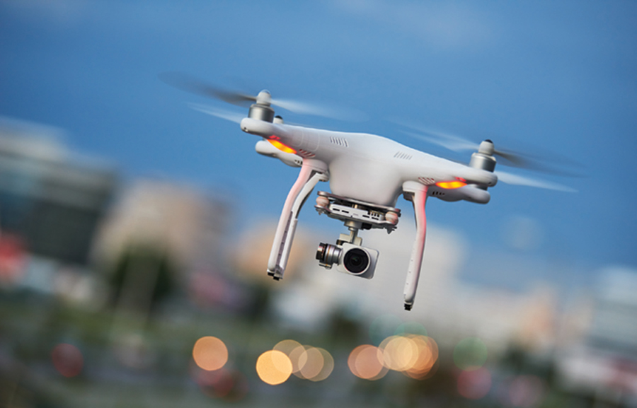
t was recently reported that one U.S. retailer had been ordered to pay a fine of nearly $3 million in connection with the marketing of drone transmitters that operated in unauthorized radio frequency bands. The severity of the fine demonstrates why manufacturers and retailers of drones need to be certain that the products they place on the market are safe and comply with relevant legislation.
The “anthropause” – the period when many countries have gone into lockdown because of COVID-19 – has been a chance for all of us to re-evaluate our lives. Many of us have appreciated the temporary respite from the noise, pollution and congestion of modern life. And, as our lives slowly begin to return to normal, we are wondering if technology can be used to make these changes more permanent.
One area that has shown considerable promise in recent years has been the expanded use of unmanned aircraft systems (UAS), more commonly known as drones. Until recently, commercially available drones were little more than toys. But that has all changed. By the time the COVID-19 lockdown began, drone technology had advanced to a point where it could successfully and safely deliver life-saving medicines to hospitals while allowing the operators to maintain strict social distancing rules.

he first part of this article (see In Compliance Magazine, October 2020) introduced the first protective equipotential bonding/grounding systems, which only had requirements for human safety. It showed how – as electronics became more commonplace and more interconnected and variable-speed motor drives increased in power – these early structures developed into bonding networks (BNs) to protect electronics from damage due to insulation failures and lightning surges. Site-wide BNs are costly to create, so in those early days it was common to only provide BNs for the parts of a site where electronic equipment was installed. This led to the development of the isolated bonding network (IBN), which is where this Part 2 picks up.
The idea of the IBN is that when fault or lightning currents occur in the rest of the building (or vehicle), their isolation prevents those currents from flowing through the nice low impedance created within the IBN, helping to protect the equipment it contains.
View Index
Antenna Measurement Techniques Association (AMTA) 2020
November 9-12
MIL-STD-810G: Understanding, Planning and Performing Climatic and Dynamic Testing
November 10-12
EMC Fundamentals
November 16-17
IEEE SPCE 2020
Advanced PCB Design for EMC & SI and Mechanical Design for EMC
November 16-18
Sensors Expo & Conference


