onducted RF immunity is a test method that subjects the equipment under test (EUT) to a source of disturbance comprising electric (E) and magnetic (H) fields, simulating those coming from intentional RF transmitters. These disturbing E and H fields are approximated by the E and H near-fields resulting from the voltages and currents caused by the test setup described in standards such as IEC 61000-4-6.
To ensure test repeatability and not cause either over or under testing, standards such as IEC 61000-4-6 have specific requirements for how the test is conducted. A small portion of the standard describes the requirements for generating the fields using a RF signal generator and power amplifier. If you’re performing commercial conducted radiated immunity tests strictly by the book, you will want to utilize a radio-frequency (RF) signal generator and power amplifier combination that fully complies with IEC 61000‑4‑6.
For the RF signal generator, this means:
If the RF signal generator on its own is not able to generate the required severity level required by the standard, then an additional piece of equipment called a broadband power amplifier (PA) is necessary to amplify the output signal from the RF generator to obtain the required test level.
The focus of the remainder of this article is on the output power characteristics of the PA required to generate a test level of 10V.
Annex E of the standard provides further guidance on selection of the PA required to generate a 10V test level. This is an informative annex, not normative, meaning it is there for clarifying purposes only, not part of the basic requirement of the standard.
Annex E states something to the effect:
Let’s cover the last item in the above requirement – the minimum coupling factor.
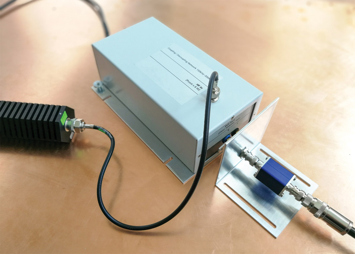
Note: Examples of coupling and decoupling devices are:
- CDNs;
- direct injection networks (with decoupling);
- clamp injection devices (EM clamps).
The minimum coupling factor (± 1.5 dB) is measured by using the output level setting circuit (see IEC 61000-4-6 for details). The coupling factor is the ratio between the output voltage, obtained when using a coupling and decoupling device in series with a 150 Ω to 50 Ω adapter and the output voltage when using two 150 Ω to 50 Ω adapters in series.
A current clamp winding with a ratio of 5:1 has a minimum coupling factor of -14 dB and the required output power of the PA is more substantial at 176 W.
An EM clamp has a minimum coupling factor of -6 dB, and the required output power is only 28 W.
As can be observed from the above, the choice of power amplifier depends a lot on what device is used for coupling and decoupling. An EM clamp is a popular choice for many test facilities and only requires a PA rated for a maximum of 28 W, however, CDN’s are the preferred coupling and decoupling devices for reasons of test reproducibility and protection of the auxiliary equipment. If you have a product with a lot of inputs and outputs, you’ll need a lot of different types of CDNs to cover all possible equipment configurations, but you won’t require a PA that needs to output too much power.
To play it safe, picking up a PA with double or triple the necessary output power will ensure you always have enough power and won’t always be running the PA at the top of its capability.
- Electromagnetic compatibility (EMC) – Part 4-6: Testing and measurement techniques – Immunity to conducted disturbances, induced by radio-frequency fields (IEC 61000-4-6:2013).
- Determine the Frequency range of operation needed, sometimes more than one amplifier is required.
- Determine if you need a Pulse or CW type of Amplifier. Example: HIRF EMC applications require High Power Pulse Amplifiers.
- Determine the minimum power needed from the amplifier. Example: As you go up in frequency, antenna gain improves, so a lower power amplifier may be acceptable.
- Assess the system losses between the amplifier and the Antenna/DUT. Example: If the test setup has 6dB of losses, then the Amplifier power needs to be 6dBm higher.
- Some modulations, if required for the test application, would require a higher power amplifier. Example: When performing an 80% AM modulation test, the amplifier needs to have 5.1dBm of margin to accommodate the peak.
- Antennas, Cables, DUTs & Rooms have cumulative VSWR. It is best to allocate for some power margin.
- Consider the application, is this a single test or will it be used repetitively.
- Consider your desired RF connection types and locations optimal for your application.
- Also consider if automation will be used so the appropriate remote capability is included.