Archaeology and XRF
EMC Concepts Explained
On Your Mark
Hot Topics in ESD

Archaeology and XRF
EMC Concepts Explained
On Your Mark
Hot Topics in ESD


ISSN 1948-8254 (print)
ISSN 1948-8262 (online)
is published by
Same Page Publishing Inc.
451 King Street, #458
Littleton, MA 01460
tel: (978) 486-4684
fax: (978) 486-4691
©Copyright 2021 Same Page Publishing, Inc. all rights reserved
Contents may not be reproduced in any form without the prior consent of the publisher.
While every attempt is made to provide accurate information, neither the publisher nor the authors accept any liability for errors or omissions.
publisher
bruce@brucearch.com
keith.armstrong@ cherryclough.com
Leo@EisnerSafety.com
ken.javor@emcompliance.com
kenrossesq@gmail.com
wernerschaefer@comcast.net
sharon.smith@incompliancemag.com.
Subscriptions outside North America are $129 for 12 issues.
The digital edition is free.
Please contact our circulation department at circulation@incompliancemag.com


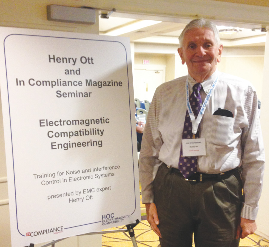
ith deep sadness, we share news of the passing of a dear friend and honored colleague, Mr. Henry W. Ott, on May 20, 2021, in Livingston, NJ.
Henry was known by many as the nation’s leading educator in Electromagnetic Compatibility design and engineering. You may have even had the good fortune to attend his class, where he got down to brass tacks and helped you develop a deep understanding of EMC engineering.
Henry earned his B.S. in electrical engineering from New Jersey Institute of Technology in 1957 and his M.S. in electrical engineering from New York University in 1963. He served three years in the U.S. Air Force, Air Research and Development Command, and served as a member of the technical staff of Bell Telephone Laboratories for 30 years. In 1970, he originated a continuing education course in noise reduction at Bell Laboratories. Henry established Henry Ott Consultants, his well-respected EMC/ESD training and consulting organization, and went on to train thousands of engineers throughout his career.
Under an Order issued by the FCC, the Emergency Broadband Benefit Program provides qualified consumers discounts of up to $50 per month on their broadband services, as well as a one-time $100 discount on the purchase of a laptop, desktop, or tablet computer from participating providers. The program is being funded by a $3.2 billion allocation initiated by the U.S. Congress earlier this year.
The FCC has engaged in an extensive outreach program to increase awareness about the Program, enlisting over 25,000 community groups and local partners to host localized events to discuss the Program specifics and its benefits.
The website purportedly set up and run by “WiFi Freedom USA” falsely claims to administer the FCC’s program and that it can provide consumers with free devices and services under the program.
The FCC’s Emergency Broadband Benefit Program was established earlier this year to provide qualified consumers with discounts of up to $50 per month on their broadband services, as well as a one-time $100 discount on the purchase of a laptop, desktop, or tablet computer from participating providers.
The FCC is encouraging those who may have provided personal information through the WiFi Freedom USA website to visit https://www.IdentityTheft.gov.


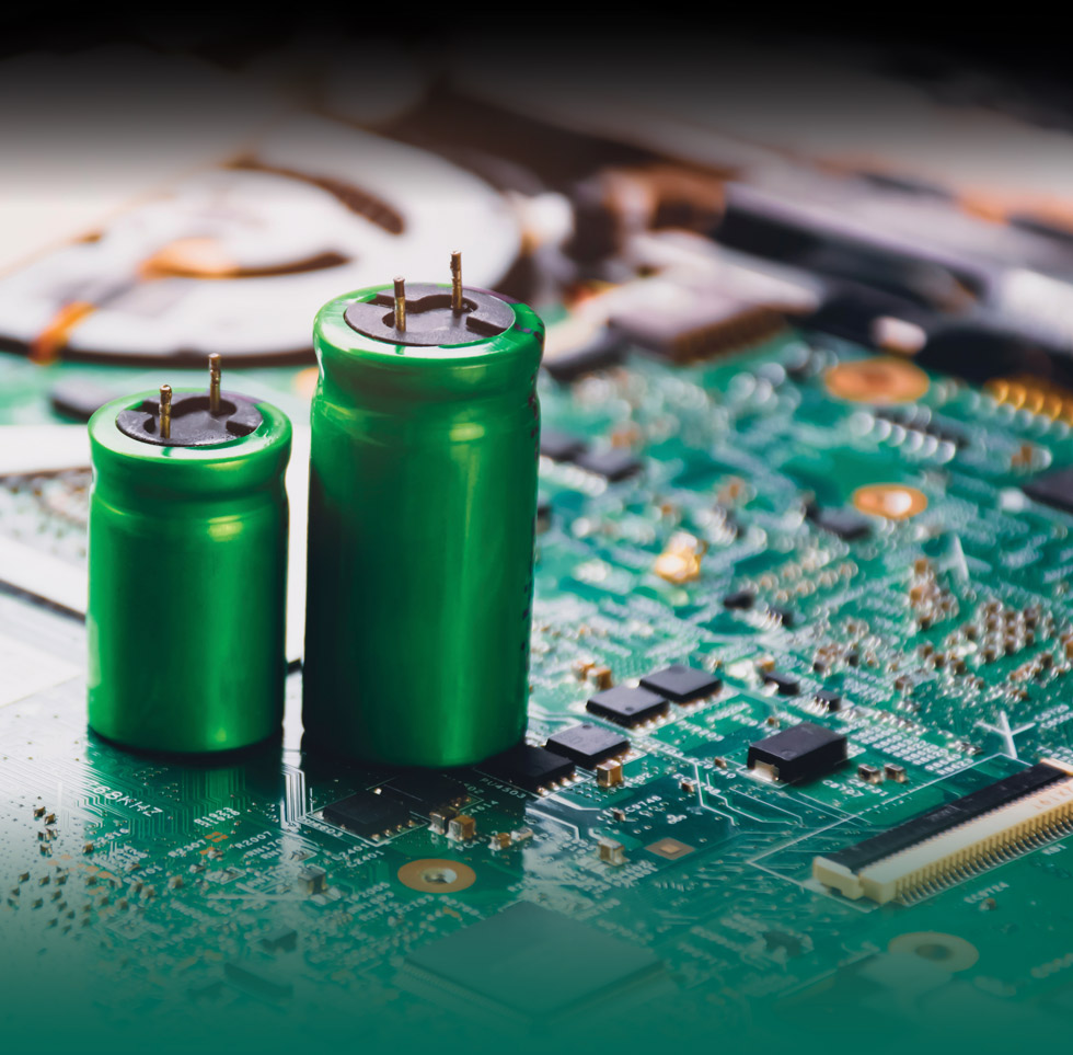
apacitors are among the most commonly used components on a circuit board. With the ever-increasing number of electronics devices (from mobile phones to cars), there has been a growing demand for capacitors. Covid 19 pandemic has disrupted the global supply chain of components from semiconductors to passive components, and capacitors have been in short supply1.
A discussion on the subject of capacitors could easily become a book or a dictionary. To start with, there are different types of capacitors such as electrolytic, film, ceramic capacitors, and so on. Then, within the same type, there are different dielectric materials. There are also different classes. As for physical construction, there are two-terminal and three-terminal capacitor types. There’s also an X2Y type capacitor which essentially is a pair of Y-capacitors packaged in one2. What about supercapacitors? The fact is, if you sit down and start reading the capacitor selection guide of major manufacturers, you could easily spend a day!


ne early contributor to semiconductor ESD research was Jack Smith of Lockheed, who was fond of stating that all ESD damage is, in the end, thermal [1]. This is because there is always conversion of electrical field energy into heat, into mechanical motion of atoms. Even in the case of voltage overstress, field energy knocks atoms out of place at defect sites, thus linking field energy to the heat equation on a microscopic scale at least.
Jack liked to start a presentation on, say, metal heating with a universal equation (Figure 1) and go from there to specific cases.
In this article, our approach will be to examine some ESD heating cases where the analysis becomes simple enough to derive significant insight and overview, without necessarily going into an extensive calculation or computer simulation. Indeed, we’ll refer to some computer simulation work that was done with much-increased efficiency due to those insights.
- Three power ratings available – 125W, 250W & 500W
- Input Voltage options – 0-150V or 0-500V
- Variety of loading sequences in single or arbitrary sequences of up to 100 steps
- High speed performance from flexible operating modes using any combination of:
– Constant Resistance (CR)
– Constant Power (CW)
- Three power ratings available – 125W, 250W & 500W
- Input Voltage options – 0-150V or 0-500V
- Variety of loading sequences in single or arbitrary sequences of up to 100 steps
- High speed performance from flexible operating modes using any combination of:
– Constant Voltage (CV)
– Constant Resistance (CR)
– Constant Current (CC)
– Constant Power (CW)


ing Solomon’s secrets may be hidden in a shard of copper slag.
How, you may ask, would we know anything about a biblical King from a blacksmith’s slag—his metallurgical waste pile?
Going deeper than you or I might, down into the slag’s elemental composition, archaeologists have discovered evidence in the last decade that King Solomon may have had smiths skilled enough to build the Kingdom of Judah described in the Bible. A baptismal basin that stood on twelve bronze bulls. A hall of cedar. A magnificent ivory throne. Who knows what could have been possible?
A vision of history illuminated by a simple tool: the XRF gun.


his is the fifth article in a series of articles devoted to the design, test, and EMC emissions evaluation of 1- and 2-layer PCBs that contain AC/DC and/or DC/DC converters, and employ different ground techniques [1-4]. In this fifth article, we are still focused on the DC/DC power converter board (2-layer PCB). In this article, we evaluate the implementation of several EMC countermeasures and present the conducted emissions results, for both voltage and current methods, according to CISPR25 Class 5 limits.
In the first article in the series, [1], we defined the overall design problem. The second article, [2], focused on the details of the 2-layer DC/DC converter design. The third article [3] presented the radiated and conducted emission results from the baseline design, which did not contain any EMC countermeasures. The results showed multiple failures in both radiated and conducted emissions. The fourth article [4] presented a systematic approach to improve these radiated failures by populating the PCB with optional EMC countermeasures on component pads that have already been designed into the PCB layout and showing their impact on the radiated emissions. The EMC countermeasures are illustrated in Figure 1 as purple dashed boxes labeled EMC-A through EMC-F.
This article discusses the impact of these countermeasures on the conducted emissions results using both the voltage and the current methods. The voltage method results are discussed first, followed by the current method results. The article concludes with a brief description of what can be expected in the next article in the series.
harged Device Model (CDM) discharge events are the major root cause for electrostatic Discharge (ESD) failures in a modern, automated production and test environment. The CDM stress testing is well established for product qualification. It simulates the possible charging of a packaged device during automated handling followed by the discharge stress event which is caused by contacting one pin with e.g., the grounded test equipment. However, due to the nature of the occurring air discharge, the CDM test shows a low reproducibility with respect to the resulting discharge pulse. The related standard [1] considers this fact by allowing a peak current variation of more ± 20 % during the tester verification process on special verification modules for pre-charge voltages below 250V. The test of real devices can show even a higher variation depending on the package and pin type. This lack of discharge repeatability can result in an expensive re-design if the device under test (DUT) does not meet the required CDM failure threshold. Thus, there is a demand for an improved repeatability stress method.
he focus of these “On Your Mark” columns is visual safety communication related to equipment, machinery, and component parts – especially the symbols and content that make up on-product labels, warnings, and instructions. While we specifically hone in on these elements, they cannot – and should not – operate in a vacuum. That’s because they’re one, intertwined component in a comprehensive product safety strategy; looking at them separately could be detrimental to the safety of the product user and to the liability risk of the manufacturer. Here, let’s explore the key components to keep in mind for your product safety strategy – from risk assessment to safety labels and manuals – and some of the ways that they all work together to improve safety and reduce risk.
“Their main duties can be summed up simply as: provide a safe product, instruct in its safe use, and warn of its hazards,” says Angela Lambert, who works with product safety teams on a regular basis through her role heading standards compliance at Clarion Safety Systems. “Executing on this throughout the design and manufacturing process, however, is much more nuanced, and mandates looking at key areas of product safety in a systematic way. This helps to ensure consistency and will situate a manufacturer in the best potential position should a liability claim arise.”
According to Lambert, these areas include:
Resource
Guide


MacArthur Compliance Services, LLC.
The process of making informed purchasing decisions can be quite complex. From absorbers to testing, today’s compliance engineer must be knowledgeable and well-versed in what to look for when selecting products and services that will work best for your needs.
This is where the Product Resource Guide comes in. In this year’s Guide, we highlight nine product categories—offer guidance on the use of these products—and selection tips on how to choose the right product or service for your applications.
So, whether you’re simply looking to replace an old piece of equipment or are fully outfitting a brand-new lab, the Product Resource Guide is here to help.
We hope you’ll find the 2022 Product Resource Guide an invaluable resource that you keep handy year ‘round.


Materials
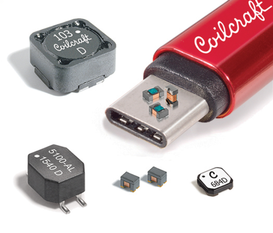
errites are frequency dependent components used to attenuate unwanted high frequency RF signals that can cause failure of emission and immunity compliance tests. There is an endless variety of form factors for ferrites, including toroidal shaped cores, clamp-on cable shells, surface mount beads, leaded through hole components for installation on printed circuit boards, and other custom shapes and sizes for use in many different types of applications.
First, determine the frequency range that needs to be attenuated. This frequency may be obtained after having performed pre-compliance testing or perhaps discovered unexpectedly during full-compliance, run for record types of compliance testing. The former situation allows for successful integration of the ferrite component into the design prior to release to production of the end product. The latter situation usually involves adding the ferrite suppression device as an after-thought, usually attaching a clamp-on type of ferrite device to external cables to suppress the RF signal and obtain passing results.
- Start with Performance. All other considerations pale in comparison to the importance of performance. For hybrid absorbers, it is important that the dielectric absorbers (pyramids and wedges) are impedance matched to the ferrite tiles.
- Make sure your absorber selection is appropriate for your application, checking for wideband performances.
- The control and predictability of measurements should be a key concern when evaluating the overall performance of the absorber under consideration. For example, for polystyrene-based absorbers, the beads are individually coated before molding. The loaded beads are randomly distributed. This results in a uniform distribution of loadings throughout the absorbers. It helps guaranteeing the chamber performance is predictable, which can meet stringent RF requirements.
- Take advantage of the superior physical/mechanical/humidity resistance properties of polystyrene-based materials, which also offer the high RF performance of traditional polyurethane absorbers.
- Consider your total cost of ownership (TCO). Don’t let the lowest initial price drive your decision. Are they durable, and will hold up to the rigors of testing over the years?
- Installation can add significant costs to your project, so look for absorber that is rigid and stable in dimension, typically made through a molding process, which are easier to install, and uniform looking.
- Are the materials water resistant, to continue working in humid environments? A closed cell structure composition provides a water resistant environment.
- Are the materials fire retardant? Protect your testing environment with materials that meet stringent fire retardant requirements
- Be confident that you adhere with growing environmental concerns and prioritize your selection for materials that are environmentally safe.
- And finally, insist that your absorber has a quality assurance manufacturing process that checks and audits each and every piece of absorber (as opposed to “batch” monitoring) before it is installed into your test environment.
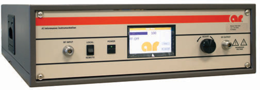
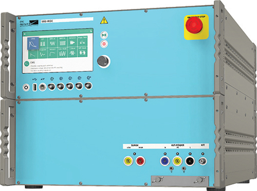
onducted RF immunity is a test method that subjects the equipment under test (EUT) to a source of disturbance comprising electric (E) and magnetic (H) fields, simulating those coming from intentional RF transmitters. These disturbing E and H fields are approximated by the E and H near-fields resulting from the voltages and currents caused by the test setup described in standards such as IEC 61000-4-6.
To ensure test repeatability and not cause either over or under testing, standards such as IEC 61000-4-6 have specific requirements for how the test is conducted. A small portion of the standard describes the requirements for generating the fields using a RF signal generator and power amplifier. If you’re performing commercial conducted radiated immunity tests strictly by the book, you will want to utilize a radio-frequency (RF) signal generator and power amplifier combination that fully complies with IEC 61000‑4‑6.
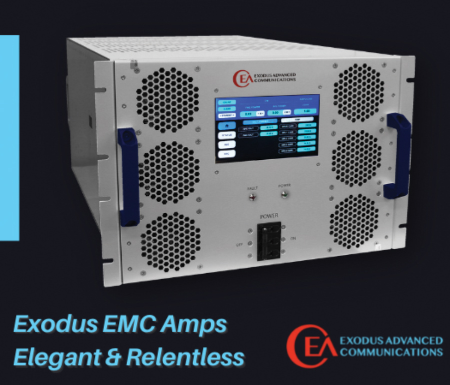
Rugged & Relentless
Rugged & Relentless
Rugged & Relentless

Las Vegas, Nevada 89120 USA
Tel: 1-702-534-6564
Email: sales@exoduscomm.com
- Determine the Frequency range of operation needed, sometimes more than one amplifier is required.
- Determine if you need a Pulse or CW type of Amplifier. Example: HIRF EMC applications require High Power Pulse Amplifiers.
- Determine the minimum power needed from the amplifier. Example: As you go up in frequency, antenna gain improves, so a lower power amplifier may be acceptable.
- Assess the system losses between the amplifier and the Antenna/DUT. Example: If the test setup has 6dB of losses, then the Amplifier power needs to be 6dBm higher.
- Some modulations, if required for the test application, would require a higher power amplifier. Example: When performing an 80% AM modulation test, the amplifier needs to have 5.1dBm of margin to accommodate the peak.
- Antennas, Cables, DUTs & Rooms have cumulative VSWR. It is best to allocate for some power margin.
- Consider the application, is this a single test or will it be used repetitively.
- Consider your desired RF connection types and locations optimal for your application.
- Also consider if automation will be used so the appropriate remote capability is included.
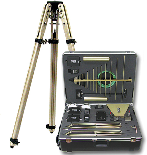
ntennas used for EMC testing possess several characteristics which make them ideal for use in a fast-paced, production-like EMC test environment. This article will briefly describe what these characteristics are, starting with the most important parameter – antenna factor.
Antenna factor units are dB/m for E-field antennas. Make sure the antenna you choose is provided with a table of the antenna factor versus frequency because in order to convert (in software) the measured voltage at the antenna terminals into the actual field strength at the antenna, you have to add the antenna factor and cable attenuation (also a function of frequency). Here is an important equation to remember in case you need to troubleshoot a problem with your measurement system not measuring correctly:
E (dBµV/m) = V (dBµV) + Antenna Factor (dB/m) + Cable Attenuation (dB) – Preamp gain (dB).
Note 1: Ignore preamp gain if a preamp is not used.

re you considering the purchase of an EMC chamber for in-house testing? If so, what factors should you consider for determining if the investment is a wise choice or if the continued utilization of a third-party test facility is the better option? For some, the decision is easy. The volume of products they intend to develop that require EMC testing is so low that the cost to bring EMC testing in-house is clearly not justified. For others, they may have a lot of new products in development (or plan to) and taking them to an outside EMC testing facility on a regular basis is not only costly, it is inconvenient and time-consuming. For those in this latter group, trying to decide if they should bring EMC testing in-house is not always a straight-forward decision.
Other ar companies: modular rf • sunar rf motion • ar europe
Other ar companies: modular rf • sunar rf motion • ar europe
for EMC Testing.


For more information on AR Amplifiers visit us at www.arworld.us/systems or call 215-723-8181.
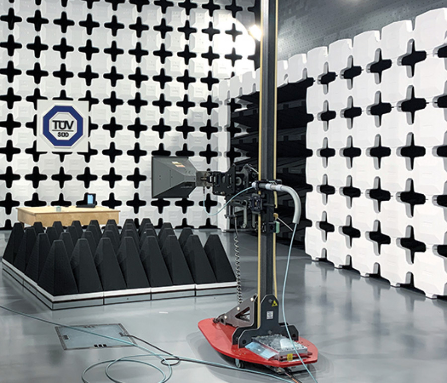
- Selection of a chamber is determined by the standard being tested to. Some types of EMC Chambers are: Commercial, MIL STD/DO-160, CISPR 25 and Reverb.
- Commercial chambers are used for IEC and CISPR standards for Emissions and Immunity testing. Typically, “Semi – Anechoic” and achieve CISPR16 (Emissions) and IEC 61000-4-3 (Immunity) chamber performance requirements.
- Semi-Anechoic Chambers are strategically lined with absorber and ferrite to meet specifications without fully lining all surfaces.
- Verification for CISPR 16 compliance is Normalized Site Attenuation (NSA) (26 MHz-1 GHz) and Site Voltage Standing Wave Ratio (sVSWR) (1‑40 GHz). This verifies the chamber “Quiet Zone”. Quiet zones are normally equal to the turntable diameter. EUT’s can’t be larger than the quiet zone.
- For compliance, variations in the quiet zone performance cannot exceed +/-4db for NSA and 6dB for sVSWR.
- Verification for IEC 61000-4-3 is a field uniformity test. Typically, a 1.5m x 1.5m vertical plane consisting of 16 points spaced 0.5 m apart is the measured area. At least 12 Points must vary by >6dB.
- MIL STD and DO-160 chambers can be Semi-Anechoic or Fully Anechoic. Standards require the absorber have a minimum absorption of 6dB from 80MHz to 250MHz and 10dB above 250Mhz. A table with a conductive top is used for testing the EUT and is bonded the shield ground.
- CISPR 25 chambers are fully lined on walls and ceiling, contain a similar table with metal lining on top, and must pass the Long Wire Test or the Reference Site Method test to meet the Standard.
- Reverb chambers rely upon the reflectivity of the walls and an internal movable paddle to reflect generated signals and increase the value of V/m generated from the transmit antenna.
- Information needed to design a reverb chamber is the lowest frequency, the test volume, maximum V/m, and standard to be tested to (MIL STD, DO, ISO).

![]()
![]()
![]()
![]()
![]()
![]()
![]()
![]()

The future is here! From driverless vehicles and drones delivering pizzas, to ear buds that act as virtual mixing boards for real-world audio, our lives are increasingly dominated by EMC. So, too, is ETS-Lindgren’s work in compliance testing and measurement, transcending the standards of EMC performance – Beyond Measure.
As an international manufacturer of market-leading components and systems that measure, shield and control electromagnetic and acoustic energy, ETS-Lindgren is the driving force that allows some of the biggest industry names, and latest technological advances, to meet compliance standards. From chambers to test cells, absorbers, positioners and antennas, ETS-Lindgren’s EMC solutions are designed for reliability, diversity, scale and precision.
More importantly, our ability to create real-world test scenarios, troubleshoot potential failures and maximize the chance of passing standards within the allotted time and budget; helps our customers bring life-changing products to market – faster.
To view our accreditations and case studies, visit our website at ets-lindgren.com.
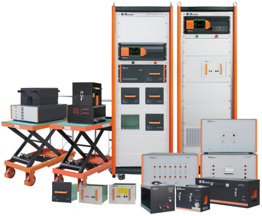
Simulators

lectromagnetic Interference (EMI) filters (also called a power line filters), are passive, frequency selective, bi-directional (two-port) networks comprised of inductors, capacitors, resistors and ferrites.
These low pass filter devices are often thought of as just components whose sole purpose is to suppress unwanted emissions emanating from the electronic devices they’re installed in, so these products can pass regulatory compliance emissions tests.
Don’t overlook the fact that EMI filters can also be used to prevent unwanted RF noise (such as electrical fast transient burst, conducted RF, and some surges) from entering susceptible devices, especially if the EMI filter is combined with proper device shielding in a kind of “belt and suspenders” approach to electromagnetic compatibility. In this case, EMI filters help make RF susceptible devices more rugged in their surrounding environments, if these environments happen to also be heavily polluted with RF noise. EMI filters come in handy when the electronic products they are paired with must comply with national and international standards for both emissions and immunity (susceptibility).

- Filters should perform in both symmetric and asymmetric mode. That is, they should remove differential and common mode noise. Some manufacturers offer comparatively smaller filters, but only specify asymmetric performance. These fail to remove differential noise.
- Filters should be rated for the appropriate maximum Line-to-Ground or Line-to-Line voltage for a 3 phase system. This eliminates the uncertainty of whether a filter will work at circuit voltages lower than the maximum filter rating.
- Filters should be rated for the appropriate circuit current and be able to withstand an overload of 140% for at least 15 minutes. This ensures the survival of the filter under overload conditions.
- Filters should be rated for low temperature rise in order to increase their durability and reliability.
- Power filters should be listed by a Nationally Recognized Testing Laboratory (e.g. UL, Intertek). This ensures that a 3rd party has approved the safety of the filters.
- When testing for avionics at 400Hz power, filters should also use Power Factor Correction Coils. This ensures that high reactive currents at 400Hz are neutralized.
- Larger power filters (above 200 Amps) should have an option to be floor standing. This ensures that most of the weight is on the stand rather than on the shielded wall.
- Protection performance for HEMP/EMP filters should be according to MIL-STD-188-125 or IEC 61000-4-24. These are the preeminent standards used today for specifying conducted Point of Entry protection.
- When protecting a facility against HEMP/EMP, it is crucial to indicate if the filters will be installed inside or outside the protective shield. Only one side of the filter has the protective elements; the protection side must be that which is exposed to the threat.
- When using electronic power sources connected to filters, the source should have a transformer in its output circuitry. This minimizes unwanted interaction with filters.


• Ferrite Kit
• On-Board Grounding Kit
• EMI Shielding Tape Kit
• Plastic Components Kit
• Thermal and Vibration Kit
Toll free (US only): 1-855-EMC-PART
International: +1-408-971-2055
Email: sales@kgs-ind.com
www.kgs-ind.com
Analyzers
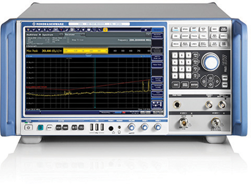
pectrum analyzers are expensive pieces of equipment that should be handled with care, especially when it involves applying signals to the RF input. Some new users may not know what “care” means and how to go about ensuring the spectrum analyzer they’re using is protected from overloading and damage. The intent of this article is to describe how not to blow up your spectrum analyzer. Those new to the subject of spectrum analyzers and measurement receivers may first want to review references 1 through 3 which cover some of the basics concerning spectrum analyzers and measuring receivers in general.
It is usually the mixer that is most susceptible to damage, followed by some of the other components identified in Figure 1.
RF Input
The RF input port (usually located on the front of the spectrum analyzer) is where the signal desired to be measured goes. Before applying any signal to this port, it is prudent to first ask ourselves, “What can we do to this input? and “What can we apply here safely?”

Laboratories
hether you’re trying to get a product through safety approval from one of the many Nationally Recognized Testing Laboratory’s (NTRLs) or having full compliance EMC testing performed at an accredited or non-accredited third-party laboratory or an internal in-house test facility, it’s imperative for successful completion of the project that as a compliance engineer or technician leading a product certification effort, you trust but verify the work of these other entities. For the remainder of the article, we’ll call these other entities “service providers.”


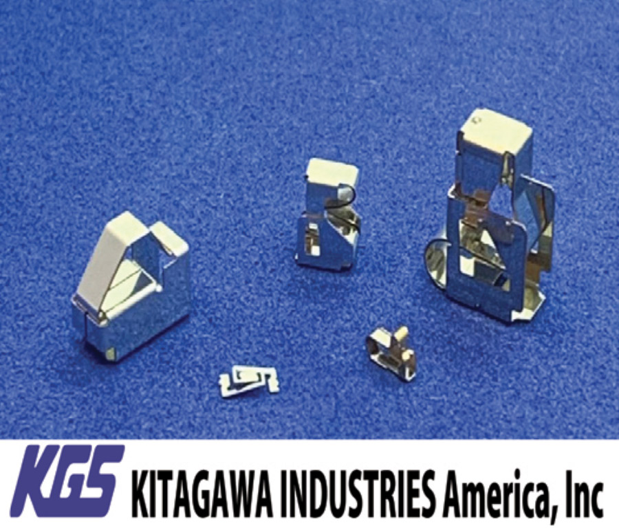
- Effective for suppressing emission and immunity reduction
- All EMC mitigation can be done at the board-level
- Space-saving and robust design
- Easy to incorporate even where screws are included
- Tape-and-reel design allows for use with automated pick-and-place machine to increase efficiency and reduce manual labor

- Combination of conductive and non-conductive materials for excellent shielding effect and environmental sealing, in one single gasket
- Thin layer of nickel graphite or silver aluminum co-extruded on to a high-performance silicone base
- Designed for 5G frequencies and will meet future shielding demands
- Offers flexible solutions in terms of material, construction, and function
- Better compression set, compared to traditional materials. The gasket will return to its original shape much more successfully than previously possible.


International Shielding Expert George Kunkel discovered a critical error: the accepted theory of electromagnetic shielding violates the basic laws of physics. This new book, the result of over 50 years of research, provides a more accurate, efficient way for design engineers to apply electromagnetic theory in the shielding of electrical and electronic equipment. Learn more at http://www.spira-emi.com.


EMC Mini
October 13
5G Antenna Systems
October 18-21
MIL-STD 810 Testing
October 24-29
AMTA 2021
Fundamentals of Random Vibration and Shock Testing
November 17-18
The Battery Show Digital Days
November 30 – December 2
The Battery Show Europe
View Index

- Learn to address Key EMI threats: Emissions, ESD, RFI, Power Disturbances & More
- Focus on what is inside the box: Components, Printed Circuit Boards, Power Electronics, Grounding, and Shielding.
- Includes over 35 Practical Design EMC Fixes!
- Participate in interactive discussions and learn from realistic scenarios
- Increase your skillset from the comfort of your home or office
- Become more confident and efficient in your product design

