EMI/RFI Shielding
Proper Heatsink Grounding
A

common question in new product development is, “How do I properly ground the heatsink?”

As a practicing compliance professional, this is an important question to have at least an idea of how to respond. Other professionals on the development team look to the compliance staff for help in developing a solution that will perform well thermally (i.e., cool the integrated circuits they’re attached to) and meet radiated emissions (RE) Class A or more stringent Class B requirements. The following summary of proper heatsink grounding is provided to better address this common issue. Let’s first discuss common problems with heatsinks.
Common Issues with Heatsinks
Common practice is to place metal heatsinks on top of high-frequency (HF) integrated circuits (ICs) to help cool them. Because the heatsinks are mounted very close to the HF emitting function of the IC, unwanted internal currents can easily couple onto the heatsink. Due to its much larger physical and electrical size, the heatsink is a very efficient radiator compared to the much smaller IC and its tiny internal bond wires.

WARNING: This could spell disaster. I have witnessed first-hand where installing a heatsink (first believed to improve margin for RE) caused a product that initially passed Class B by a couple of dBs to fail Class A by over several dB! This likely occurred because, with the installation of the metal heatsink, internal IC currents were allowed to parasitically couple onto the heatsink, and in turn, the heatsink performed just like an efficient antenna, radiating (or re-radiating, if you will) HF from the IC and allowing RE limits of the test to be exceeded.

Where to Ground the Heatsink?
Another common practice is to “ground” the heatsink to the printed circuit board (PCB) ground-reference-pale (GRP). Doing so will reduce the voltage difference between the heatsink and the ground reference plane, thereby helping to reduce emissions.
How Many Ground Points are Required for the Heatsink and Where?
This is where the rubber meets the road, and a key to ensuring the metal heatsink performs more as a shield to HF from the IC and less like an efficient antenna that allows HF noise from the IC to be radiated into space.

Pro Tip: As technology progresses, the frequencies we’re dealing with also increase. This means the heatsink size becomes electrically larger, resulting in a more efficient radiator. Carefully planned and designed heatsink grounding is mandatory if it is to be effective at shielding these higher frequencies.

Reference 1 describes measurements conducted from 100 MHz to 10 GHz with a common heatsink topology using several different grounding points. Ideally, we would like to have an infinite number of grounding points located around the heatsink to gain the lowest impedance path possible between the heatsink and the GRP. However, we must make a trade-off since we don’t have an infinite amount of real estate surrounding the IC that we can consume. We will have to settle for a few grounding spots instead of an endless number of them. But how few can we get away with? At the other end of the extreme, if there aren’t a sufficient number of grounding points, the emissions at some frequencies can increase. The table included below is intended to help the reader visualize published research results.
Heatsinks
Conclusion

After reviewing Table 1, it becomes apparent that emissions levels are significantly impacted by the number of ground points installed between the heatsink and the GRP. Depending on the number of contact points, some emissions in specific frequency ranges go up, while at the same time, emissions go down in other ranges. The zero-, one- or two-point contact grounding scheme doesn’t buy you much, and the eight-point method buys you quite a bit. All configurations have a primary resonance that can be moved around if it also falls on the first or second harmonic of the process clock frequency.

Heatsink Grounding Configurations vs. Near Field Emission from Heatsink
Note 1: Ground contact points are small metal posts (~ 25 mm x 25 mm) connected between ground plane and heatsink.

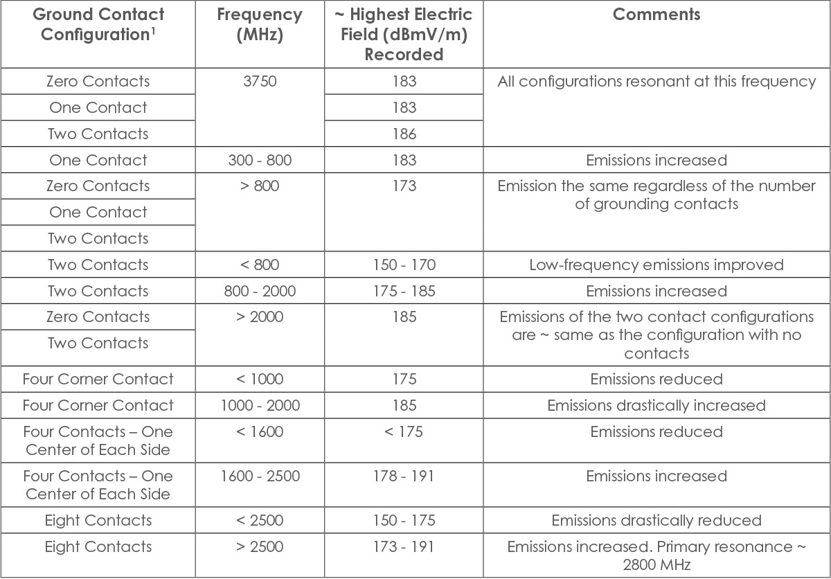
Table 1: Heatsink Grounding Configurations vs. Near Field Emission from Heatsink

References and Further Reading
  1. Archambeault, B.R., PCB Design for Real‑World EMI Control, Kluwere Academic Publishers, 2002
Share this story: