Duty to Warn Non-English Speaking and Reading Product Users
Getting the Best EMC from Shielded Cables Up to 2.8 GHz Part 2
Duty to Warn Non-English Speaking and Reading Product Users
Getting the Best EMC from Shielded Cables Up to 2.8 GHz Part 2


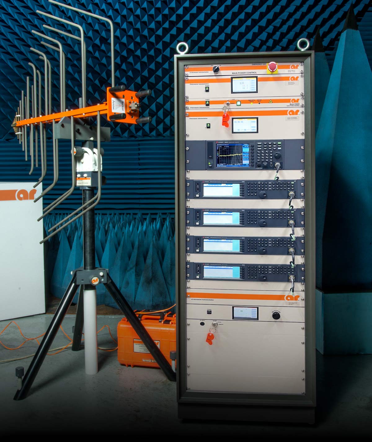
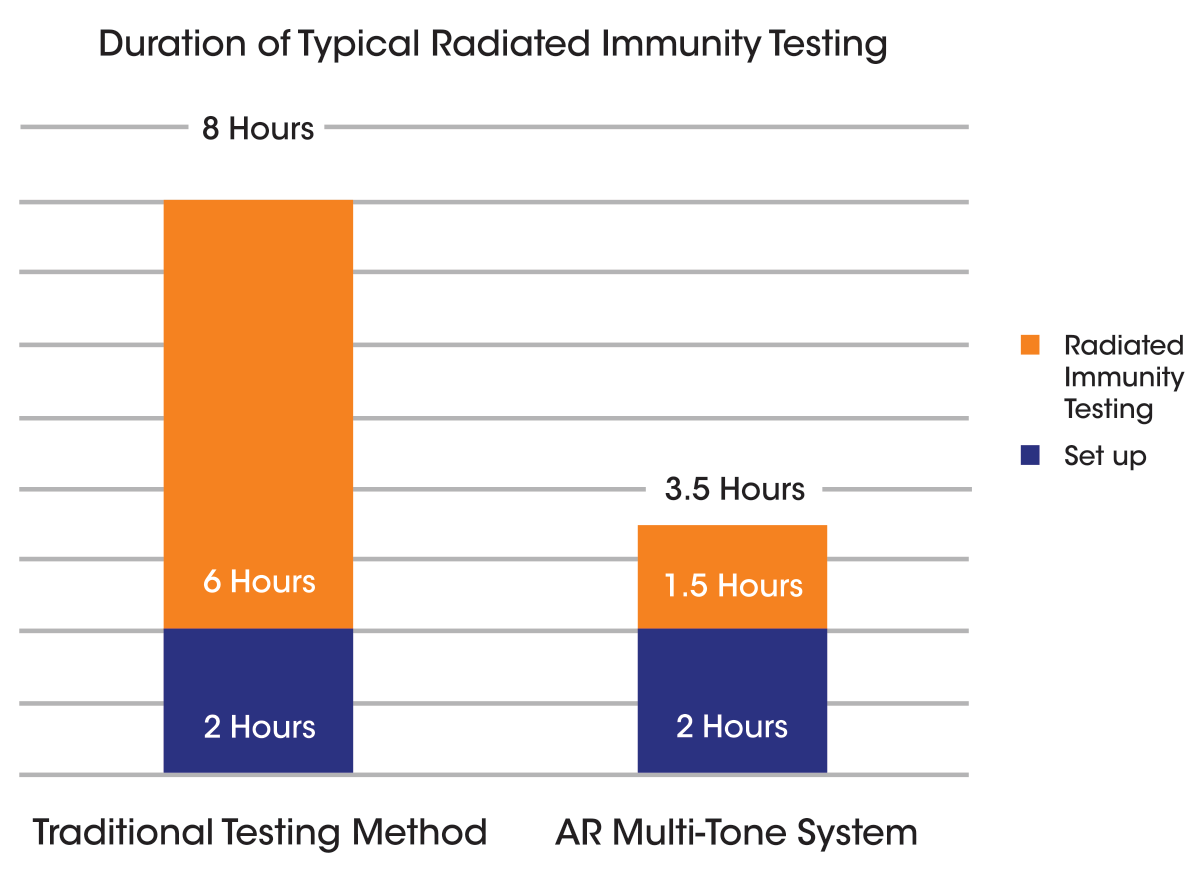
Testing Time by More Than 50%
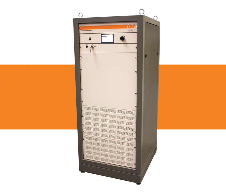
For example, AR’s Multi-Tone System can reduce the typical time to run traditional tests such as IEC 61000-4-3, ISO 11451, and ISO 11452, by over 50%. In the event of an EUT failure, margin investigation and traditional single tone testing is easily performed through AR’s emcware® software.
This is a creative way to help your company be more profitable by using your assets more efficiently.


ISSN 1948-8254 (print)
ISSN 1948-8262 (online)
is published by
Same Page Publishing Inc.
451 King Street, #458
Littleton, MA 01460
tel: (978) 486-4684
fax: (978) 486-4691
©Copyright 2022 Same Page Publishing, Inc. all rights reserved
Contents may not be reproduced in any form without the prior consent of the publisher.
While every attempt is made to provide accurate information, neither the publisher nor the authors accept any liability for errors or omissions.
publisher
bruce@brucearch.com
keith.armstrong@
cherryclough.com
Leo@EisnerSafety.com
dgerke@emiguru.com
ken.javor@emcompliance.com
kenrossesq@gmail.com
wernerschaefer@comcast.net
Subscriptions outside North America are $129 for 12 issues. The digital edition is free.
Please contact our circulation department at circulation@incompliancemag.com


According to a recent article posted on the website of Scientific American, researchers working at the Federal Laboratories for Materials Science and Technology in Switzerland have published a paper describing a water-activated paper battery made from environmentally friendly materials. The battery reportedly consists of the same key components as standard batteries, but the anode and cathode elements consist of inks that have been printed on the front and the back of a piece of paper…
In a Notice published in the Federal Register in mid-August, the agency announced…

How 6G Will Transform Our Lives

ith the global deployment of 5G networks still underway and many areas of the world still using older and less advanced communications networks, researchers and industry leaders are already looking ahead to 6G and its potential benefits. Following the 10-year development timelines of previous cellular technologies, we could expect 6G trials and deployments as early as 2030. But much work is ahead of us in these coming eight years to develop relevant standards that address the needs that are evident today and those that will reveal themselves in the coming years. To this end, the IEEE Standards Association (IEEE SA) is at the forefront of efforts to define 6G technology.
The high-level vision for 6G is to deepen the connection and integration between the digital, physical, and human worlds. While it’s too early to know what final form 6G will take before it is standardized, we can speculate on the characteristics the next generation network will have, including the technologies that will be included and why they are important.


hen it comes to energy-related products,1 sustainable product policy in the European Union (EU) is largely implemented through the ecodesign and energy labeling legislative frameworks. Product-specific laws have been adopted under each framework. For example, various household appliances are the subject of individual EU Regulations concerning ecodesign2 and energy labeling. In all, about 30 product groups are regulated through some 50 measures.
While the legislative frameworks have been in place for many years, they have also been subject to periodic review and updating. For instance, the 2017 adoption of the EU Energy Labelling Framework Regulation came with the repeal of the 2010 Energy Labelling Framework Directive and the introduction of obligations associated with a product database – later known as the European Product Database for Energy Labelling (EPREL).


he duty to warn and instruct is a significant duty in the United States. Under U.S. product liability law, liability can result if a manufacturer or product seller fails to adequately communicate appropriate safety information to purchasers and users of its products.
Given the considerable number of languages spoken and read in the United States and the significant number of people who do not speak English or are illiterate, developing a method to effectively communicate safety information to readers of product labels and instruction manuals is an important consideration. Adequate safety communications that are not effectively communicated to foreseeable users may arguably be considered defective.
This article will describe the relevant law and the voluntary U.S. technical standards concerning the use of foreign languages in safety information and will provide recommendations to manufacturers about using multilingual labels and instructions, including the use of new technology to better transmit such information.
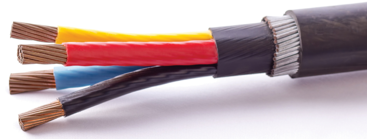
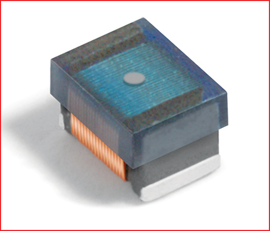
n Part 1 of this article, I shared with you the origins of my journey to assess the shielding effectiveness (SE) of screened1 cables and discussed some basic rules for terminating cable shields. In Part 2, I’ll summarize the testing I recently conducted on various approaches to improving the shielding effectiveness of screened cables used in high-frequency applications and the results from that testing.


Resource
Guide


MacArthur Compliance Services, LLC.
The process of making informed purchasing decisions can be quite complex. From absorbers to testing, today’s compliance engineer must be knowledgeable and well-versed in what to look for when selecting products and services that will work best for your needs.
This is where the Product Resource Guide comes in. In this year’s Guide, we highlight nine product categories—offer guidance on the use of these products—and selection tips on how to choose the right product or service for your applications.
So, whether you’re simply looking to replace an old piece of equipment or are fully outfitting a brand-new lab, the Product Resource Guide is here to help.
We hope you’ll find the 2023 Product Resource Guide an invaluable resource that you keep handy year ‘round.


Materials
ou’re the compliance lead for your company’s latest, newest, fanciest widget, just about to be released to production, with anticipated sales in the millions. The product has an extremely high profit margin and customers from all around the world are waiting in line to make a purchase.
So, what are your next steps? The pressure is on high, full-throttle! The beads of sweat are starting to form on your forehead. What do you do to solve this problem in the shortest amount of time possible? Don’t even think board spin. A board spin this late in the game will take too long and is therefore off the table as a solution.
he 2020 edition of IEC 61000‑4‑3 contains several significant technical changes.
- testing using multiple test signals has been described;
- additional information on EUT and cable layout has been added;
- the upper frequency limitation has been removed to take account of new services;
- the characterization of the field as well as the checking of power amplifier linearity of the immunity chain are specified.
The focus of this article is the checking of the power amplifier linearity as pointed out in item d above.

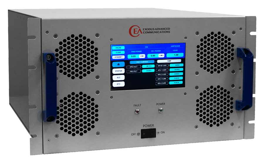
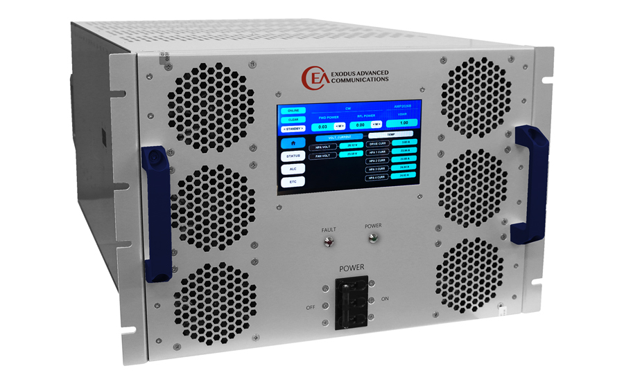
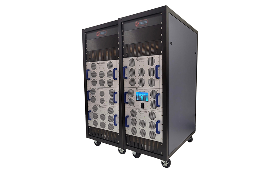
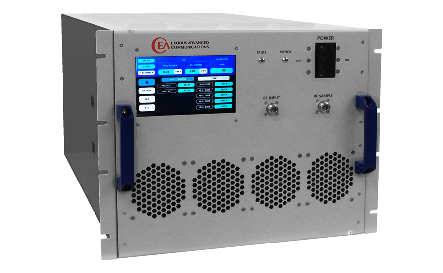
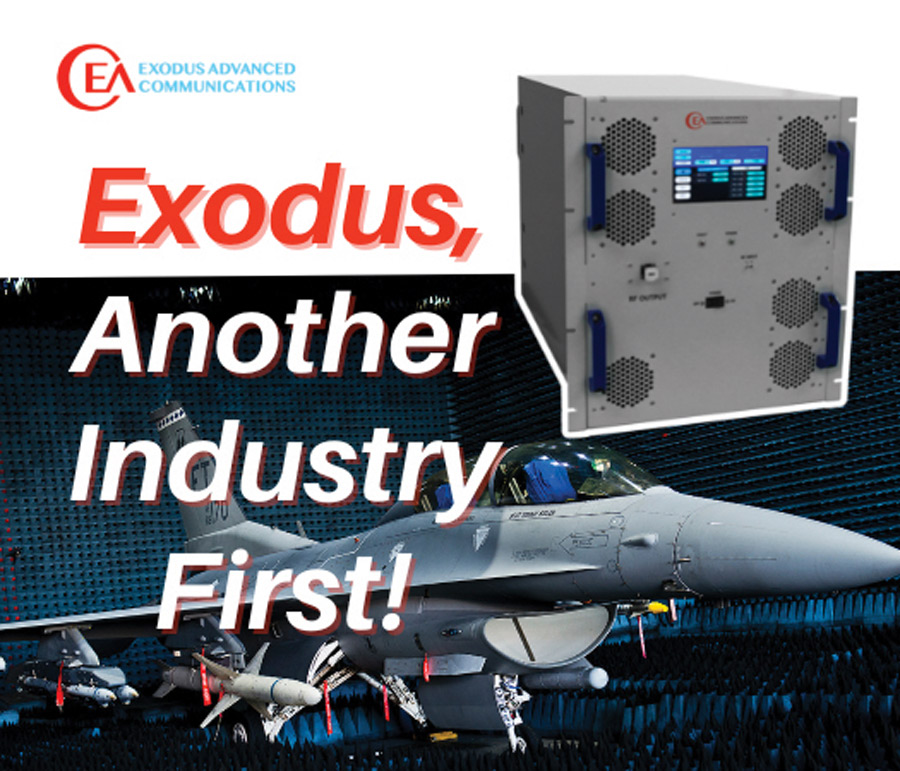
26.5-40.0GHz, 200W
Another Industry First!
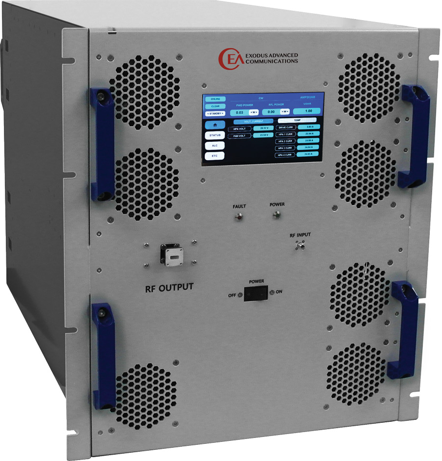
Ingenuity!

Las Vegas, Nevada 89120
Tel: 702-534-6564
Email: sales@exoduscomm.com
- Determine the frequency range of operation needed, sometimes more than one amplifier is required.
- Determine if you need a Pulse or CW type of amplifier. Example: HIRF EMC applications require high power pulse amplifiers.
- Determine the minimum acceptable linear or saturated power needed from the amplifier. Harmonics should be considered based on the frequency range. Example: As you go up in frequency antenna gain improves so a lower power amplifier may be acceptable but the higher gain of the antenna may affect the Harmonic Level.
- Assess the system losses between the amplifier and the antenna/DUT. Example: If the test setup has 6dB of losses then the Amplifier power needs to be 6dBm higher.
- Some modulations if required for the test application, would require a higher power amplifier. Example: When performing an 80% AM modulation test the amplifier needs to have 5.1dBm of margin to accommodate the peak.
- Antennas, cables, DUTs, and rooms have cumulative VSWR, it is best to allocate for some power margin. Example: working into a 2:1 requires 12% more forward power.
- Consider the application, is this a single test or will it be used repetitively?
- Consider your desired RF connection types and locations to be optimal for your application.
- Consider if automation will be used so the appropriate remote capability is included.
s a compliance engineering professional, you may encounter situations when you must consider how multiple and often conflicting requirements apply to your product and how to deal with them effectively.

- Selection of a chamber is determined by the standard being tested to. Some types of EMC Chambers are: Commercial, MIL STD/DO-160, CISPR 25 and Reverb.
- Commercial chambers are used for IEC and CISPR standards for Emissions and Immunity testing. Typically, “Semi – Anechoic” and achieve CISPR16 (Emissions) and IEC 61000-4-3 (Immunity) chamber performance requirements.
- Semi-Anechoic Chambers are strategically lined with absorber and ferrite to meet specifications without fully lining all surfaces.
- Verification for CISPR 16 compliance is Normalized Site Attenuation (NSA) (26 MHz-1 GHz) and Site Voltage Standing Wave Ratio (sVSWR) (1‑40 GHz). This verifies the chamber “Quiet Zone”. Quiet zones are normally equal to the turntable diameter. EUT’s can’t be larger than the quiet zone.
- For compliance, variations in the quiet zone performance cannot exceed +/-4db for NSA and 6dB for sVSWR.
- Verification for IEC 61000-4-3 is a field uniformity test. Typically, a 1.5m x 1.5m vertical plane consisting of 16 points spaced 0.5 m apart is the measured area. At least 12 Points must vary by <6dB.
- MIL STD and DO-160 chambers can be Semi-Anechoic or Fully Anechoic. Standards require the absorber have a minimum absorption of 6dB from 80MHz to 250MHz and 10dB above 250Mhz.
- CISPR 25 chambers are fully lined on walls and ceiling, contain a similar table with metal lining on top, and must pass the Long Wire Test or the Reference Site Method test to meet the Standard.
- Reverb chambers rely upon the reflectivity of the walls and an internal movable paddle to reflect generated signals and increase the value of V/m generated from the transmit antenna.
- Information needed to design a reverb chamber is the lowest frequency, the test volume, maximum V/m, and standard to be tested to (MIL STD, DO, ISO).


hould the reference (i.e., ground) plane be split into two separate sections and a ferrite bead installed between them to prevent unwanted radio frequency emissions? Let’s examine why this practice is not a good idea and should be avoided at all costs.
Splitting the Reference Plane
The 0V reference plane (sometimes mistakenly called a ground plane) is an essential element in electromagnetic compatibility (EMC) design of a PCB. Its proper design is more important than almost anything else that can be done to the board to achieve EMC compliance. DO NOT split the reference plane unless you know what you are doing (and maybe not even then).
Although it should be kept as one congruent element to achieve EMC compliance, beware that you will encounter EMC design guidelines and application notes for integrated circuits which still describe the old practice of splitting the reference plane between analog and digital sections, and then bridging them with a ferrite bead, as the best thing to do to achieve EMC compliance.

and
Test Labs
wo questions that often arise in and around engineering research and development cubicles, watercoolers, and office spaces are:
- How does signal integrity (SI) compare to electromagnetic compatibility (EMC) and vice versa? and
- Which of the two is the tougher design challenge (SI or EMC)?
- How does signal integrity (SI) compare to electromagnetic compatibility (EMC) and vice versa? and
- Which of the two is the tougher design challenge (SI or EMC)?
The following article addresses these two very common questions involving two inter-related and specialized sub-fields within the realm of compliance engineering.
common question in new product development is, “How do I properly ground the heatsink?”

n previous Product Insights articles (References 1 through 7), we’ve primarily addressed filtering and shielding topics separately. While the two are important foundational topics, it’s time to take a deeper look into our roles as product developers toward the goal of achieving the most robust (lowest EMC emissions, high EMC immunity) product design possible at the highest frequency of concern in the system we’re developing.
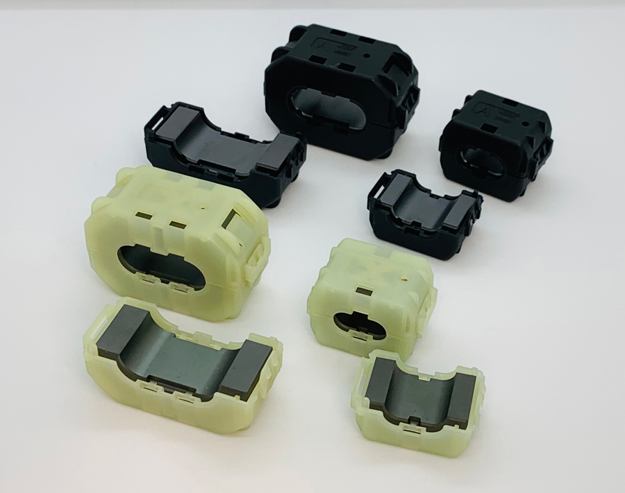

Email: sales@kgs-ind.com
Phone: (408) 971-2055
US Toll Free: 1-855-EMC-PART
he calculation of creepage and clearance distances (spacings) is one of the most important activities a product safety/compliance engineer or technician performs throughout the product development process.
Conducting this activity sooner rather than later is key to releasing a product on time and within schedule and budget constraints. Waiting to calculate creepage and clearance distances until the prototype stage, when safety evaluation and testing have begun, is almost always a recipe for disaster. Correcting spacing miscalculations late in the product development cycle will assuredly add unnecessary redesign and retest efforts, increase the risk of delaying production release until the issue is addressed, or even releasing the product without the necessary product safety approvals.
If you work on a technically savvy design team, they will likely turn to you for help in determining the appropriate spacings for the product far in advance of ordering any prototypes. If they do not come to you for help, then it would be wise to take the lead and supply this information even if not requested.

hose who may be looking for a signal integrity (SI)/power integrity (PI) simulation software package should have an idea of what functionality and other characteristics they can expect from such a tool during both pre-layout design and post-layout design.
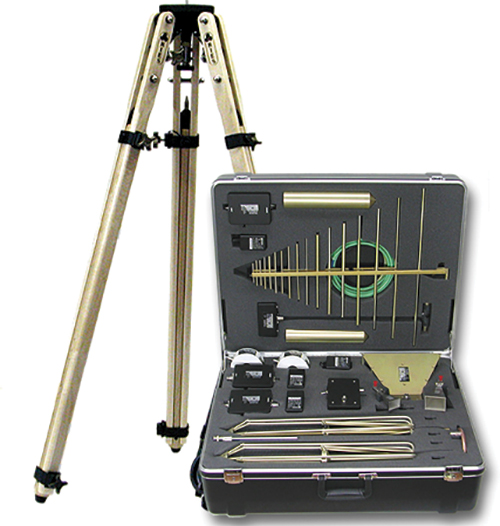
AK-40G Antenna Kit 20 Hz- 40 GHz
A.H. Systems’ AK-40G Portable antenna kit offers the best frequency range and performance in one case. This is the antenna kit you need for everyday testing. Just grab it and go. Inside the case is all the reliable antennas, current probes, and cables needed to satisfy a wide array of customer requirements. The antenna kit also comes with a tripod with azimuth and elevation head for antenna positioning and a tripod carrying case. Excellent performance, compact size and a lightweight package make this kit a preferred choice for field-testing and can ship with next-day, on-time delivery. Other antenna kits available.

- Do you know what standards are required?
- Do you own a copy of the standards?
- Do your design engineers know the standards and how to comply?
Answer “NO” to any of these questions? You need to contact CertifiGroup. We will help you all the way! That includes performing the entire certification process in our 25,000 sq. ft. test lab. On time, on budget! Contact us today at 800-422-1651.

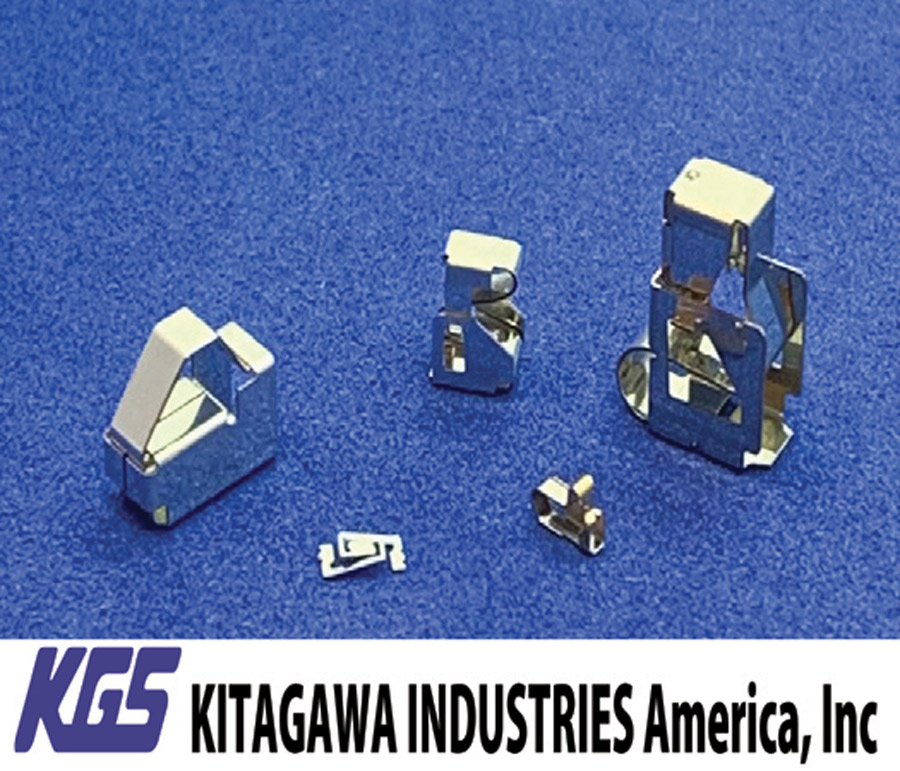
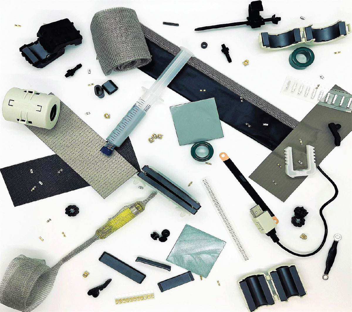
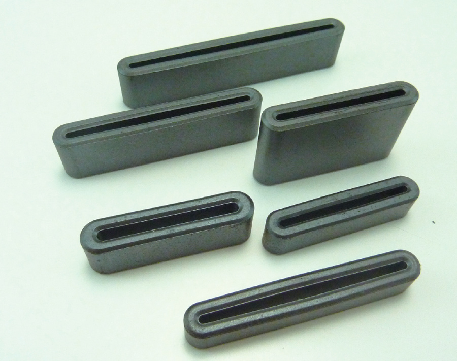
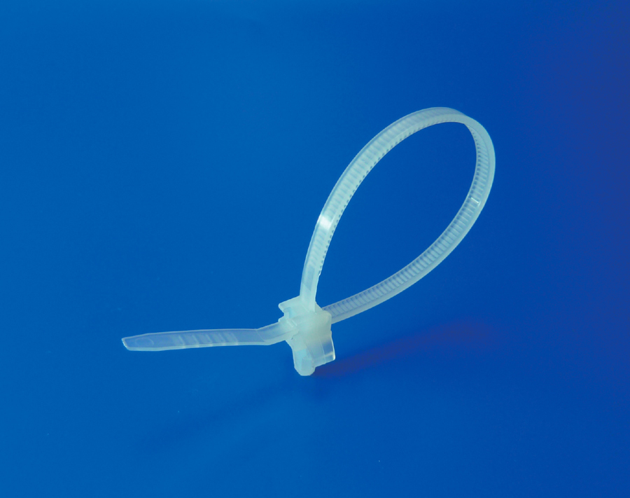
- Effective for suppressing emission and immunity reduction
- All EMC mitigation can be done at the board-level
- Space-saving and robust design
- Easy to incorporate even where screws are included
- Tape-and-reel design allows for use with automated pick-and-place machine to increase efficiency and reduce manual labor
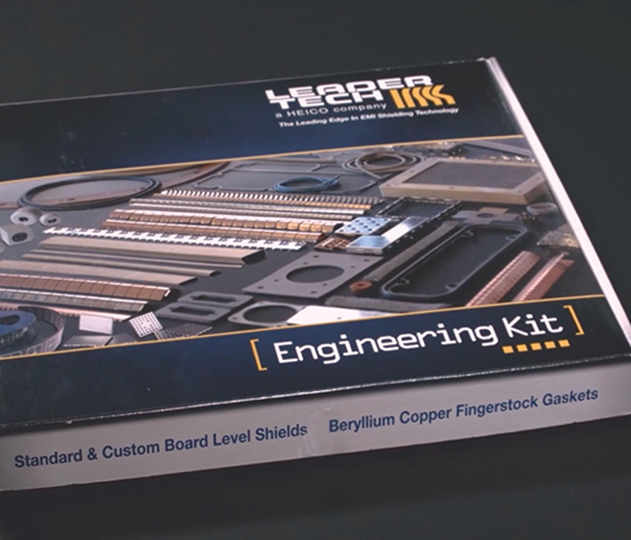
Questions? 866-832-4364 or email sales@leadertechinc.com

Vitrek New DL Series Electronic DC Load

his article discusses the reflections on a transmission line at a shunt resistive and capacitive discontinuity along the line. The analytical results are verified through the HyperLynx simulations and laboratory measurements.
Note that the transmission line is matched at the source, and the resistive discontinuity and the load resistor values are equal to the characteristic impedance of the line.
When the switch closes at t = 0, a wave originates at z = 0, [1], and travels towards the discontinuity. At the time, t = T this wave arrives at the discontinuity. The transmission line immediately to the right of the discontinuity looks to the circuit on the left of the discontinuity like a shunt resistance equal to the characteristic impedance of the right line [2].
Part 1
Integrated circuits intended for automotive applications have higher electrostatic discharge (ESD) qualification requirements than those intended for commercial and consumer electronics. This article is in two parts. Part 1 will discuss why electronic components intended for automotive applications might require more stringent requirements and then review the high-level differences between conventional ESD qualification and automotive qualifications. Part 2, to be in next month’s issue of In Compliance, will give the specific additional requirements for human body model (HBM) and charged device model (CDM) for automotive qualification.
(This article had its origin in a series of blog posts on ESD testing available at http://www.srftechnologies.com/ESD-RESOURCES.html.)
Automobiles have always had electrical circuits. Even before electric headlights and electric starters, magnetos provided electrical pulses to power spark plugs. The amount of electrical circuitry increased steadily over the years, and today, the radio was replaced long ago as the most sophisticated piece of electronics in a vehicle. The rapid expansion in the high-tech electronic content in automobiles has attracted increased interest across a much wider section of the electronics industry than in the past. Integrated circuit suppliers wishing to become suppliers to the automotive industry must become familiar with the qualification requirements for automotive electronics.
n AM radio can be useful for finding both radiated emissions and ESD events. The biggest advantage of using a radio in EMC engineering is its cost (A second-hand AM radio on eBay costs about 20 USD or less). Understanding how radio works is essential for engineers to use this low-cost technology to troubleshoot complex EMI issues.
Using an AM Radio to Locate Emission Sources
The client’s product was a large-size installation located at their factory site. To perform an in-situ EMC test on the EUT, they shut down most of the equipment and lighting during the weekend, but the ambient noise at the site was still large enough to cause issues. Even when the EUT was powered off, the ambient environment exhibited a noise level higher than the limit line defined by the standards (in this case, the EUT was being tested against defense standard DEF STAN 59-411). This can be clearly seen in the results while performing a low-frequency radiated emission scan using a rod antenna (see Figure 1).

During the testing of one aircraft we suffered a very marked and complete electrical failure of the aircraft (much to the alarm of both the test engineers and the cockpit crew) which turned out to be due to the EUT we were testing being next to the ground power supply controller which didn’t like the field…
A new grocery store had been opened in St Louis, MO. This new “high-tech” (now normal) store included the installation of 15 scanning checkout stands with customer enunciator panels. A week before the big grand opening, store management turned on the new checkout stands to verify their functionality…
In April of 2004 I installed a new HVAC system to include a Honeywell EAC F300 Electronic Air Cleaner. Immediately, I noticed on channel 9 off-air TV lines of ‘snow’. I subsequently found out that the air cleaner was causing this problem. I checked the air-cleaner’s electrical power supply outlet…
A groundbreaking patented protection product that helps prevent accelerated skin aging caused by electromagnetic waves and daily environmental pollution. With Clarins exclusive Magnetic Defence and Anti-Pollution Complexes, this gentle, refreshing mist invisibly shields skin, prolonging…
I suppose my two worst ‘banana skins’ were a shopping centre in Leeds and a big manufacturing company in Germany. The shopping centre was a four car VF (variable frequency motor-drive) group of elevators that had been working fine for 3 years and then blew £3,000 worth of central traffic dispatching computer. I was asked to take a look, spent 3 days on site and found 180 earth faults – which was a shock as this installation had been checked for earth loop impedance…
I’ve been doing some EMC training for our customers and one very interesting story came out about a circa 1990’s control system with a VF controller. There’s a notice on the outside of the controller to say no mobile phones because entering the cubicle with a 3G phone causes both IGBT’s to fire at the same time causing a huge bang as two phases join together momentarily before the HRC fuses blow…
Mobile phone masts are something that most people do not want erected close to where they live. As a result of this, phone companies will on occasion approach building owners to see if they would lease space within a building to enable a transmission mast to be erected. If its location is out of sight so much the better as residents will be unlikely to know of its existence and will therefore be unlikely to object…


View Index
Grounding & Shielding
October 6-7
Fundamental Principles of Electromagnetic Compatibility and Signal Integrity
October 9-14
44th Annual Meeting and Symposium of the Antenna Measurement Techniques Association (AMTA)
October 11-14
Applying Practical EMI Design & Troubleshooting Techniques
Advanced Printed Circuit Board Design for EMC + SI
Mechanical Design for EMC
Military Standard 810 (MIL‑STD 810) Training
October 18
2022 San Diego Test Equipment Showcase
November 1-4
Applying Practical EMI Design & Troubleshooting Techniques
Advanced Printed Circuit Board Design for EMC + SI
Mechanical Design for EMC
November 7-11
EMC Week

