Evaluation of Automotive Electronics Product Development Process

Evaluation of Automotive Electronics Product Development Process


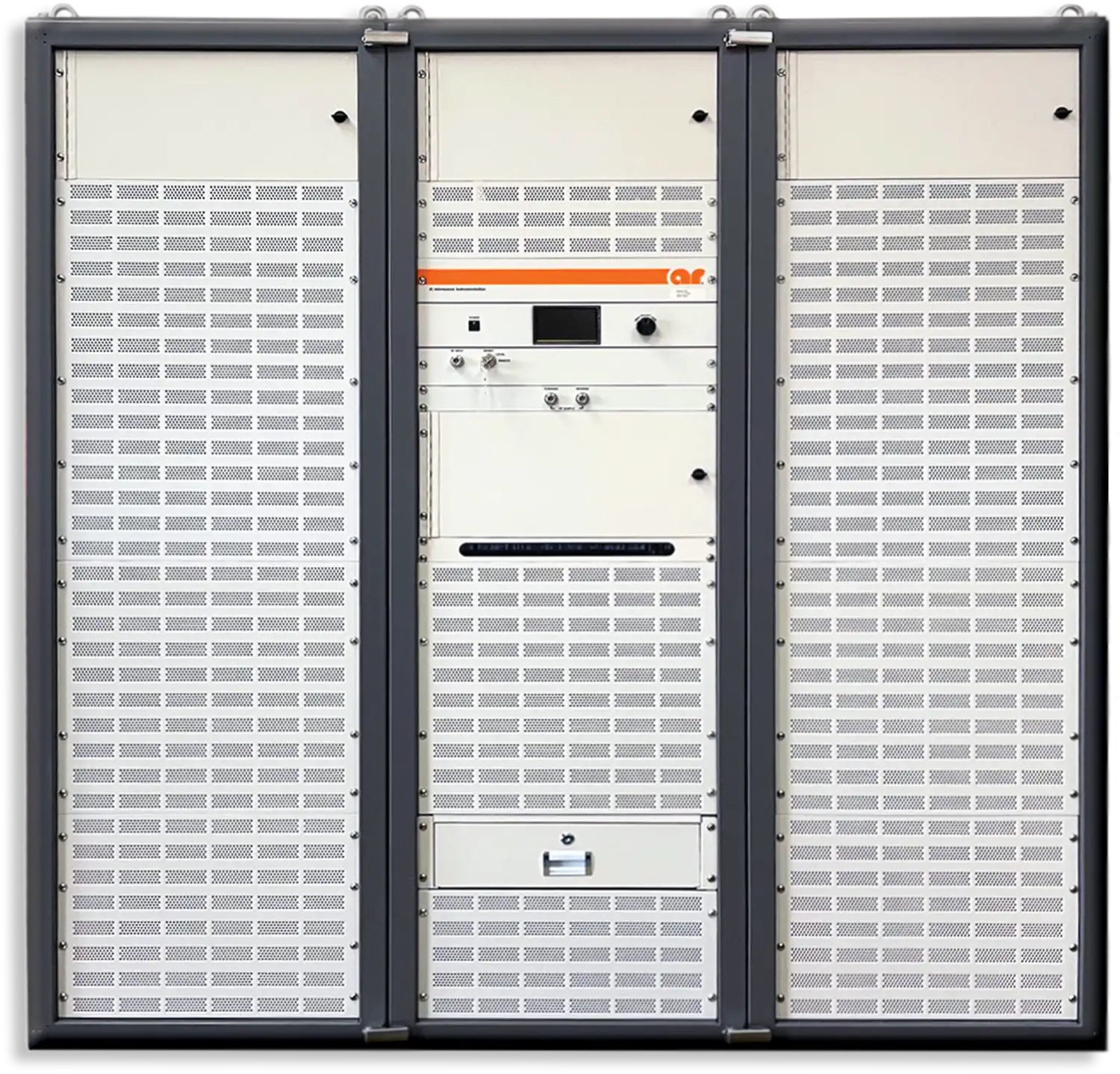
For more information on AR Amplifiers, visit www.arworld.us
Or contact us at info@arworld.us & 215.723.8181
ISSN 1948-8254 (print)
ISSN 1948-8262 (online)
is published by
Same Page Publishing Inc.
451 King Street, #458
Littleton, MA 01460
tel: (978) 486-4684
fax: (978) 486-4691
© Copyright 2024 Same Page Publishing, Inc. all rights reserved
Contents may not be reproduced in any form without the prior consent of the publisher. While every attempt is made to provide accurate information, neither the publisher nor the authors accept any liability for errors or omissions.
editor-in-chief
Please contact our circulation department at circulation@incompliancemag.com
In this special issue, we highlight seven product categories—and offer guidance on choosing and using the right products and services for your applications.

Contributing Author


The WHO’s report, “The effect of exposure to radiofrequency fields on cancer risk in the general and working population,” is a meta-analysis of the findings of 63 different studies published in 22 countries around the world between 1994 and 2022. Each of the studies reviewed by WHO investigated the health effects of exposure to radio frequency-electromagnetic fields (RF-EMF) generated by mobile phones…
A Report and Order issued by the Commission establishes initial service rules applicable to wireless communications technologies that support UAS control and operations. Specifically, the rules allow UAS operators to obtain frequency assignments in a portion of the 5 GHz band intended for use by non‑networked operations…

 Visit In Compliance’s booth at these events!
Battery Japan
October 3
EU Regulatory Update for Electronics Producers 2024 Webinar
October 7-9
EMC COMPO 2024
October 7-10
The Battery Show
October 8- 9
2024 IEEE Symposium on Product Compliance Engineering
October 10
Cyber-Security Webinar
October 15
2024 San Diego Test Equipment Symposium
October 22-25
Applying Practical EMI Design and Troubleshooting Techniques
46th Annual Meeting and Symposium of the Antenna Measurement Techniques Association
October 28-October 31
Military Standard 810 (MIL-STD-810) Test Training
November 5-7
XIV Electromagnetic Compatibility Course
November 15
IoT Applications
November 20-22
Battery Japan
December 3-5
Fundamentals of Random Vibration and Shock Testing Training


https://www.element.com/connected-technologies/battery-testing-services

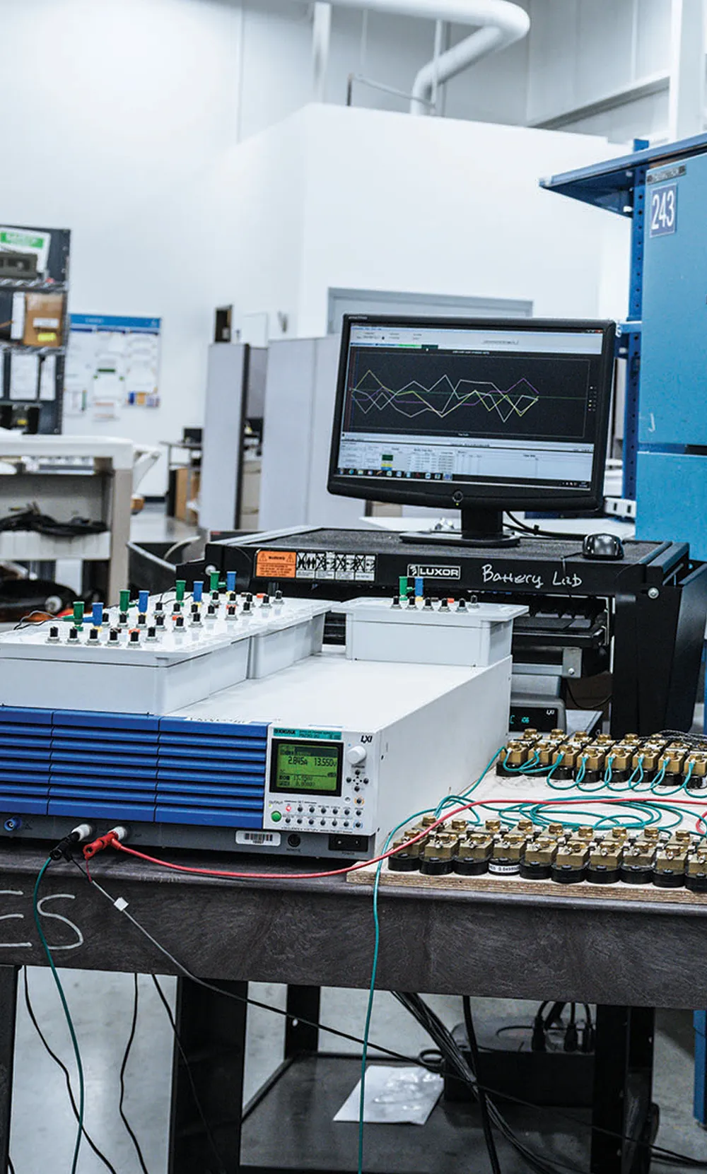
Technical Director, Battery

evision 3 of UNECE Regulation No. 100 (R100) imposes a number of new and updated requirements on manufacturers of rechargeable electrical energy storage systems (REESS) designed for use in motor vehicles manufactured, sold, or operated in the European Union and other countries.
R100 now includes a new overcurrent test and adjusted requirements on the system-on-chip (SOC) level, as well as new requirements relating to thermal propagation. All of these are intended to ensure the integrity and safe operation of such systems under anticipated operating conditions, as well as to provide a higher level of safety for vehicle drivers and passengers.
Although these updated requirements will increase the compliance burden for battery manufacturers, they will also ease the acceptance and use of battery packs with type approval, thereby broadening the market for manufacturers. In this article, we’ll provide a summary of the requirements and the benefits likely to accrue to battery manufacturers.
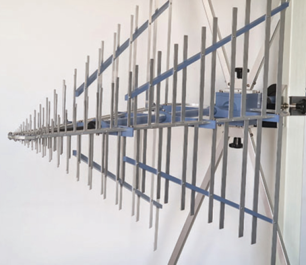
ear-field measurements are widely recognized as a highly accurate and versatile technique for testing antennas. The theory behind these measurements has been known for many decades. Indeed, in the 1960s, the company Scientific Atlanta marketed planar near-field systems where the Fourier transform operation was performed via operational amplifier circuits [1]. In the 1980s, spherical near-field measurements were introduced [2]. Since those days, especially in the past 25 years, these measurement techniques have become one of the preferred approaches for testing a broad range of antennas. Today, there are hundreds of near-field antenna test facilities installed across the globe, attesting to the method’s proven effectiveness and significance.
The acceptance of these methods and techniques was the driver behind the creation of the IEEE Standard 1720TM, “Recommended Practice for Near-Field Antenna Measurements” (IEEE Std 1720, see Figure 1.)
When it was initially approved in 2012, IEEE Std 1720 was a completely new standard developed by the IEEE Standards Association Standards Board (SASB). But advancements in technology and emerging developments over the past decade have made a revision necessary to ensure the document remains current. Further, the IEEE Standards Association (SA) mandates that all currently-active standards must be revised every ten years. For these reasons, the IEEE-SASB approved project authorization request (PAR) P1720 in 2019 for an SASB working group to undertake a revision of the original standard. To accomplish this task, a Working Group (WG) was formed under the Antennas and Propagation Society Standards Committee (APS/SC).


have spent most of my engineering career (50 years) at an automotive original equipment manufacturer (OEM), a Tier 1 electronics supplier, and as a consultant who has worked with over 40 different companies. I have observed that the quality of the product development process (PDP) and the experience of the design and test staff vary widely among different OEMs and suppliers.
There are a number of factors that impact the efficiency and effectiveness of the development process. Some examples are short design cycles, increasing complexity, staff reductions (including the most experienced people) and cost-cutting. However, there are also a number of things that are holding progress back including “we’ve always done it this way.”
There is such a large test infrastructure (equipment manufacturers, test labs, large OEM/vendor departments) that it is extremely difficult to change the PDP. OEMs all have similar testing specs which must be contractually met – these are minimum requirements. However, there are things that can be done to improve the process.


Resource
Guide
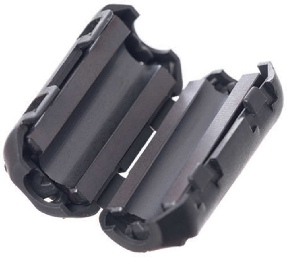
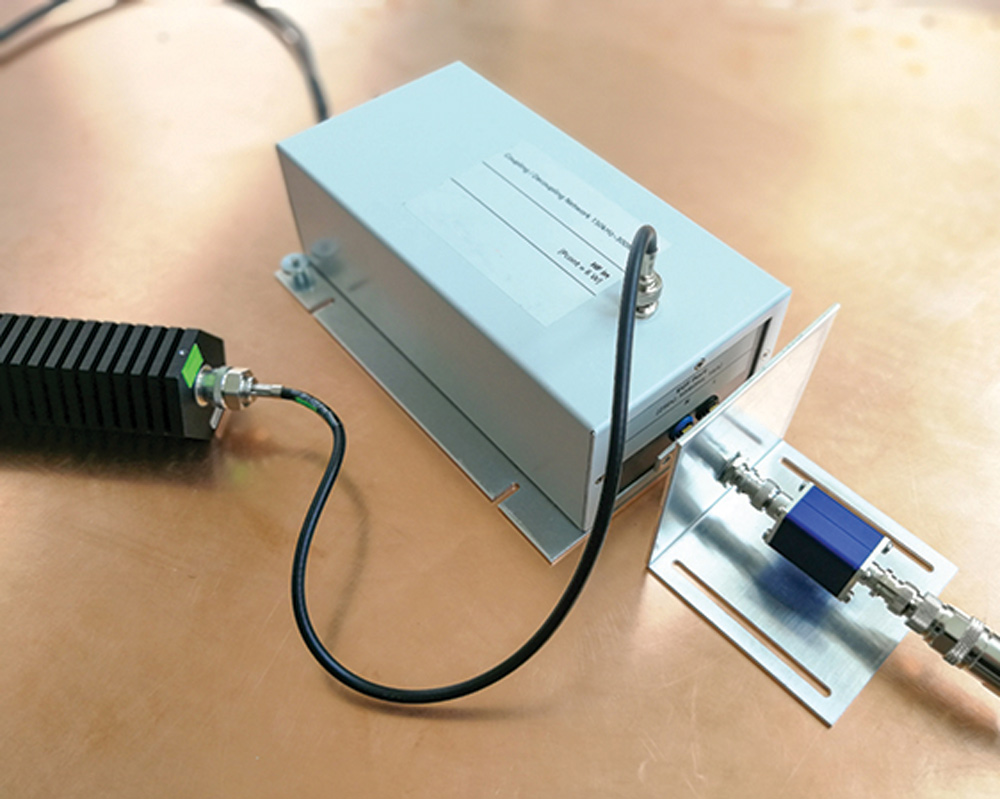
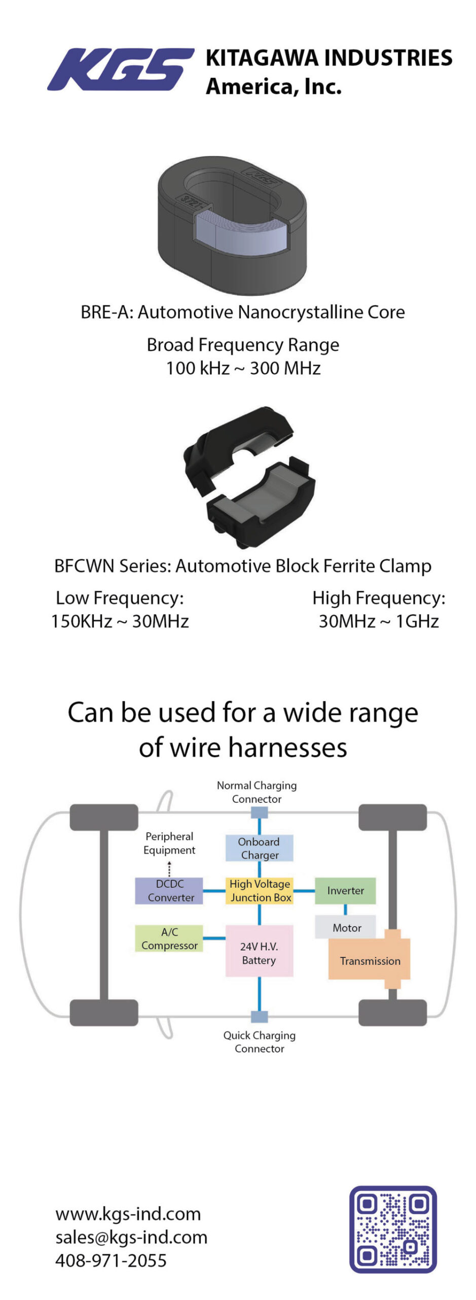
A ferrite bead, also called a ferrite choke or ferrite core, serves as a passive electronic component used for noise suppression and filtering in circuits. It achieves this by dissipating high-frequency currents within a ferrite ceramic. When installed on power pins of digital circuits, ferrite beads effectively suppress high-frequency signals.
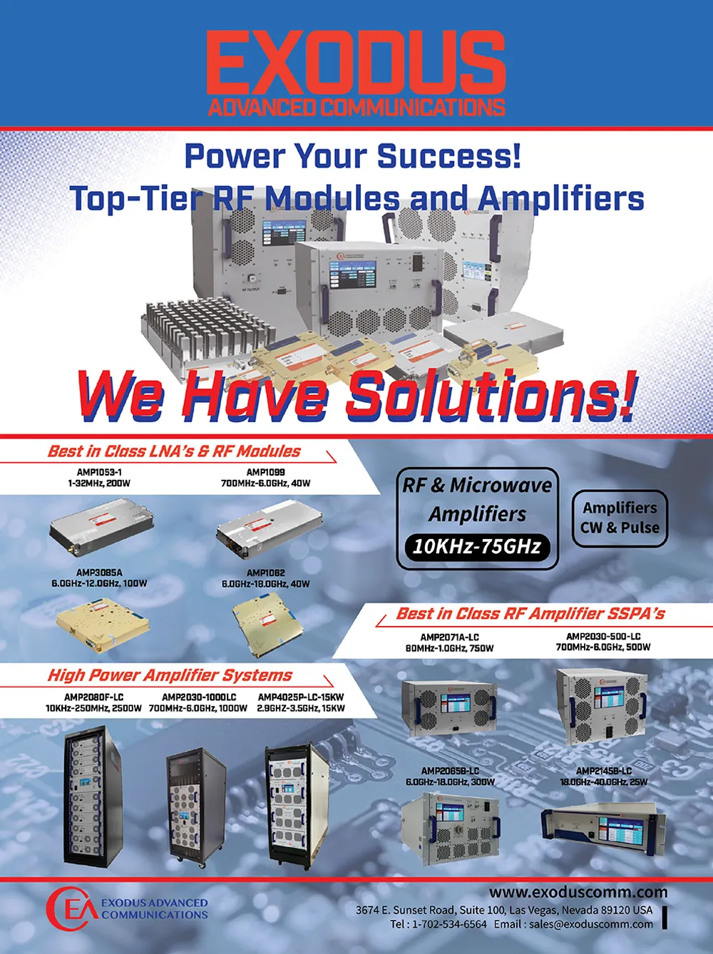
Pro Tip: No matter what – always carefully read the datasheet/specifications before deciding to purchase any amplifier!
Determine if you need a Pulse or CW type of amplifier. Example: HIRF EMC applications require high power pulse amplifiers.
Determine the minimum acceptable linear or saturated power needed from the amplifier. Harmonics should be considered based on the frequency range. Example: As you go up in frequency antenna gain improves so a lower power amplifier may be acceptable but the higher gain of the antenna may affect the Harmonic Level.
Assess the system losses between the amplifier and the antenna/DUT. Example: If the test setup has 6dB of losses then the Amplifier power needs to be 6dBm higher.
Some modulations if required for the test application, would require a higher power amplifier. Example: When performing an 80% AM modulation test the amplifier needs to have 5.1dBm of margin to accommodate the peak.
Antennas, cables, DUTs, and rooms have cumulative VSWR, it is best to allocate for some power margin. Example: working into a 2:1 requires 12% more forward power.
Consider the application, is this a single test or will it be used repetitively?
Consider your desired RF connection types and locations to be optimal for your application.
Consider if automation will be used so the appropriate remote capability is included.

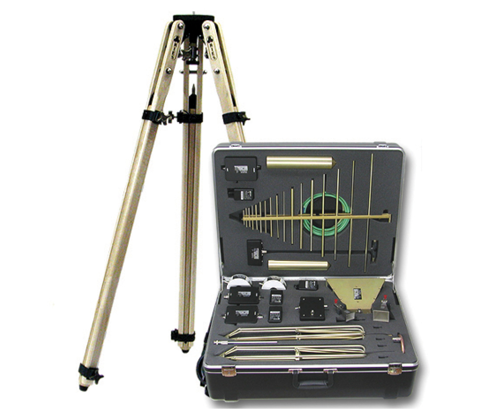
To calculate AF, two pieces of information are required: 1) λ, which is wavelength in meters, and 2) antenna gain (G) as a power ratio. Once this information is known, then AF is calculated using this basic formula:
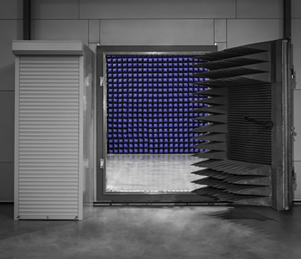
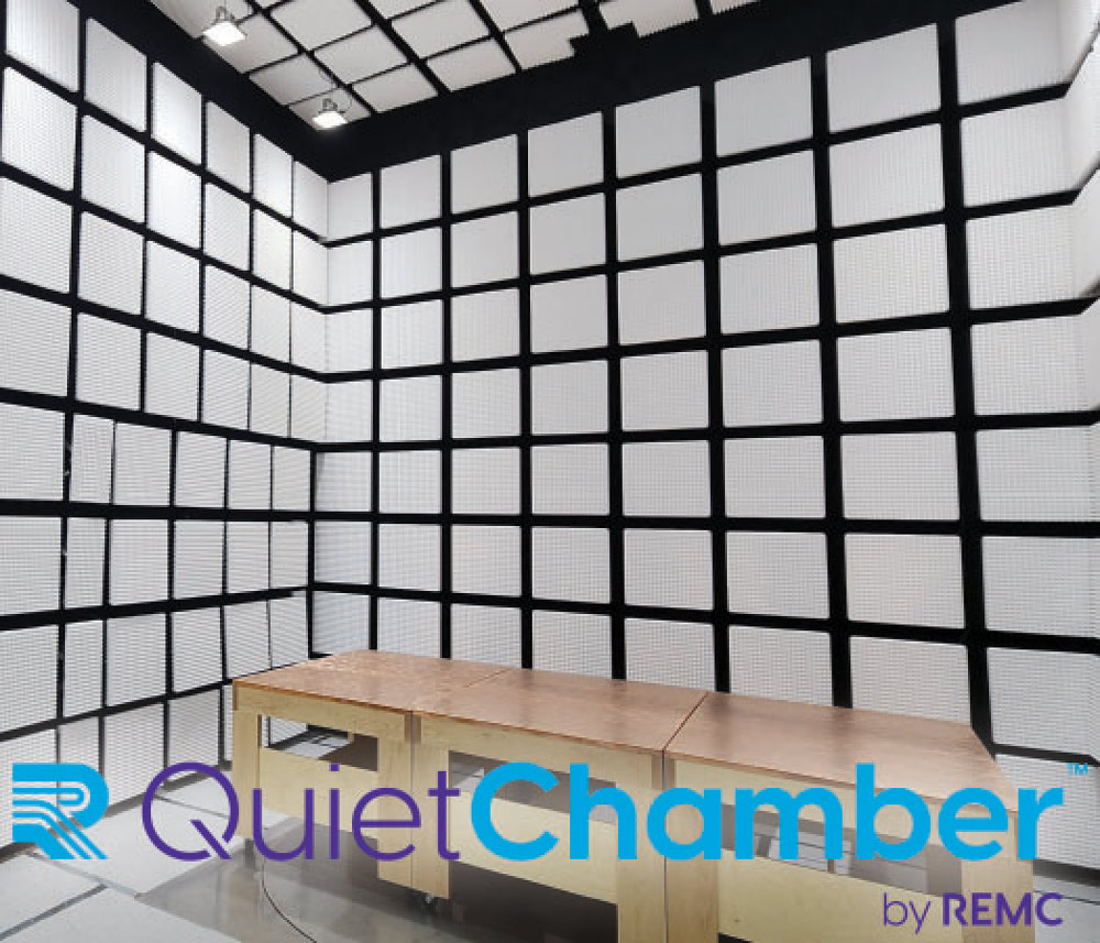
Consider the shape, size, weight, type, and heat generation of devices intended to be tested. Ensure that the chamber dimensions can comfortably accommodate the devices under test.
If the chamber will be installed in an existing facility, choose a layout that conforms to space limitations and constraints imposed by the parent room.
A chamber manufacturer can help navigate local permitting requirements, fire suppression systems, seismic approvals, structural supports, emergency features, safety systems, and design for extreme environmental conditions.
The type, size, placement, and number of RF shielding doors should be decided based on frequency of personnel access and the expected movement of devices under test.
Explore options for chamber accessories and test equipment including turntables, antenna masts, test tables, crane or hoisting systems, shielded cameras, ramps, and more.
Assess connections to the parent building for electrical, HVAC, and fire suppression systems.
Determine if a control room, raised floor, or other custom configuration is required for cable management.
A modular chamber design that allows for customization, expansion, upgrades, or potential relocation, can help expand test capabilities and adapt to future needs.
To extend the usable lifetime of the chamber and to ensure performance, regular preventative maintenance and chamber validation testing are essential.
Courtesy of
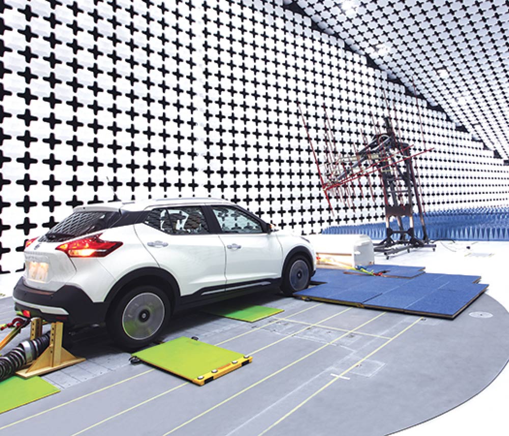
Consider the size of the device under test (DUT) as full vehicle DUTs vs component level DUTs influence the chamber size and cost.
Consider the frequency range when looking at test chambers for ADS, V2X, and OTA applications.
Become familiar with and follow the automotive industry trends to be prepared for future test requirements.
Consider a retrofit/upgrade of an existing chamber.
If a new chamber, evaluate design options for various component or full vehicle test needs.
Be aware of the challenges associated with current and quickly developing sensor and antenna technologies extending traditional automotive EMC testing.
Don’t overlook anechoic absorber: consider options for optimal performance, durability, and cost-effectiveness.
Don’t underestimate the importance of a dynamometer.
Use BIM to facilitate design and construction, stay on budget, and meet schedule deadlines.

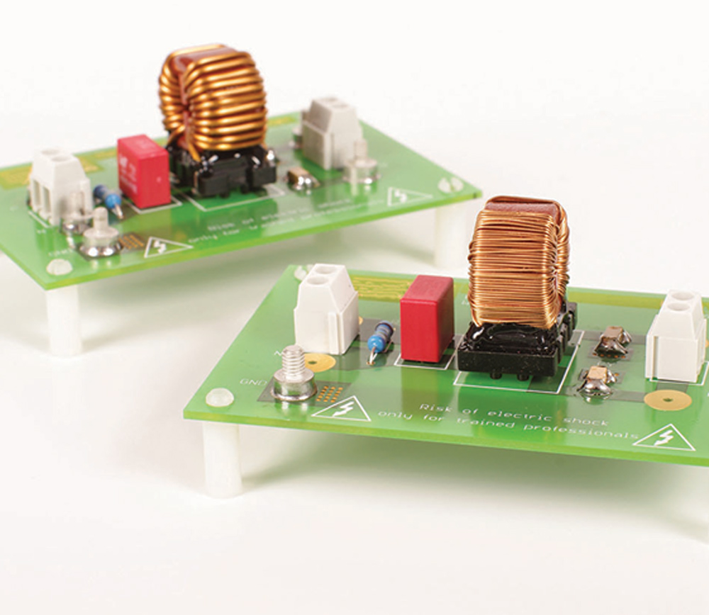
It is crucial to account for their non-ideal, parasitic characteristics when using passive components to mitigate electromagnetic interference (EMI). You might encounter situations where you initially attempt to employ a component to suppress an unwanted signal, only to discover that it does not yield the expected results. This discrepancy often arises due to the component’s non-ideal behavior.
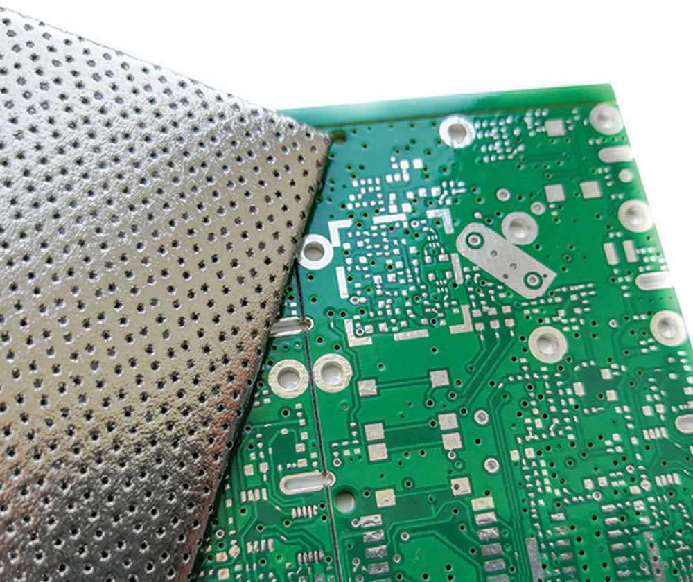
This article provides insight into how shielding is used in product development, in particular the effectiveness of shielding when it is applied at the PCB level.
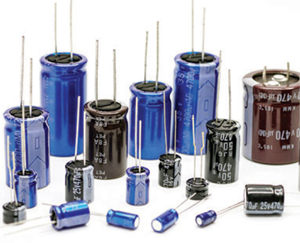
Capacitor Impedance and Frequency
- The relationship between capacitor impedance (Z) and frequency (f) is fundamental. Impedance refers to the opposition a capacitor offers to the flow of alternating current (AC).
- As frequency changes, so does the impedance of a capacitor. This behavior is depicted in Figure 1.
- Keep in mind that impedance is not just about the electrostatic capacitance (denoted as C). Other factors or components come into play.


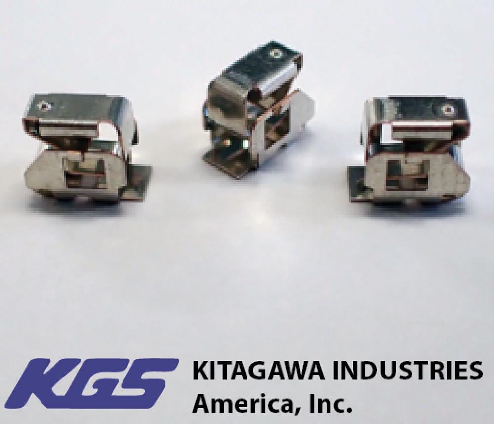
- Made of durable Beryllium Copper and surface treated with Tin reflow plating (primary plating is Copper).
- High operating temperature (-40°C – 150°C) to withstand harsh automotive environments.
- Tested for 10 million deflections at 100 compressions/second.
- Connectors are prone to static electricity, when the contact is placed near the connector a ground connection is created with the chassis to release the static electricity.


his is the first of three articles discussing four different circuit models of transmission lines in sinusoidal steady state. All four models, while equivalent, serve a different purpose. Model 1 is used to present the solution of the transmission line equations. It serves as the basis for the remaining three models. Model 2 is best suited for the introduction of the standing waves. Evaluation of the minima and maxima of the standing waves is mathematically most expedient using Model 3. The location of the minima and maxima of the standing waves is determined using Model 4. This article discusses Model 1 and Model 2 and their usefulness.
Model 1, shown in Figure 1, was discussed in [1, 2] and is briefly reviewed here.


s your semiconductor fab certified to S20.20? If yours is like most fabs, the answer is likely no. This is because the ESD controls needed in the front-end fabs are different from the back-end processes for which S20.20 was primarily written.
Several semiconductor fab representatives have stated that their customers have requested that they provide proof and/or certification that their established ESD/ESA control program is sufficient for their respective semiconductor manufacturing processes. Wafers, as they are being built, are typically more susceptible to electrostatic attraction (ESA) of particles than to damaging electrostatic discharge (ESD). However, they can still be damaged by ESD events, particularly those with the extreme energy seen when no static control principles are applied. In some cases, electrostatic fields in excess of 20,000 volts can be found in wafer fabrication facilities when no static control principles are used. Attenuation of these fields can reduce not only the risk of damaging ESD events but also a reduction of ESA onto critical surfaces.
At home.
on the go.
n our most recent “On Your Mark” columns, we’ve focused on ANSI Z535 – the U.S. standards that create a guide for the design, application, and use of signs, colors, and symbols intended to identify and warn against hazards and for other accident prevention purposes. These standards, along with their international counterpart, ISO 3864-2, can be effective starting points in helping you to develop adequate warnings. The standards are intended to be guidelines, not prescriptive instructions for the right symbol or content choices for your product or situation. And, that’s why implementation can be tricky; you need to understand the standards and best practices and then apply them in a way that works best for your product and its audience. In this column, we’ll look at the practical implications of implementing a “wordless” approach to your safety labels or safety label program.
You can do that here.
View Index