his is Part 4B of seven devoted to the topic of shielding to prevent electromagnetic wave radiation. The first article [1] discussed reflection and transmission of uniform plane waves at a normal boundary. The second article, [2], addressed the normal incidence of a uniform plane wave on a solid conducting shield with no apertures. The third article, [3], presented the exact solution for the shielding effectiveness of a solid conducting shield. In Part A of the fourth article [4], Version 1 of the approximate solution was derived. In this article, a more practical Version 2 of the approximate solution (obtained from Version 1) is presented.

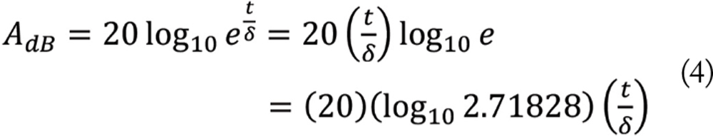
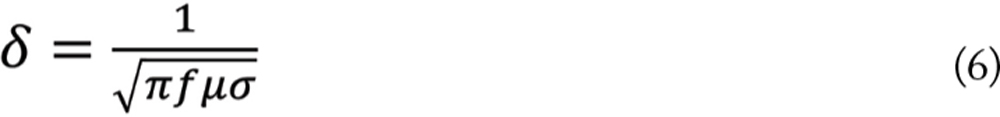
Now, let’s derive an alternative expression for the absorption loss. The exact formula was given by Eq. (11) in [4] as


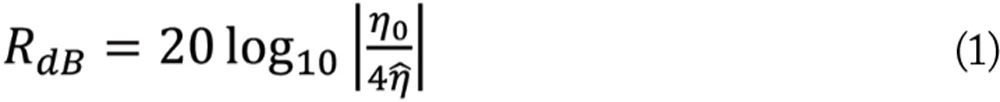
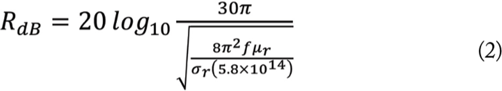
The total shielding effectiveness is


- Bogdan Adamczyk, “Shielding to Prevent Radiation – Part 1: Uniform Plane Wave Reflection and Transmission at a Normal Boundary,” In Compliance Magazine, June 2025.
- Bogdan Adamczyk, “Shielding to Prevent Radiation – Part 2: Uniform Plane Wave Normal Incidence on a Conducting Shield,” In Compliance Magazine, July 2025.
- Bogdan Adamczyk, “Shielding to Prevent Radiation – Part 3: Far-Field Shielding Effectiveness of a Solid Conducting Shield – Exact Solution,” In Compliance Magazine, August 2025.
- Bogdan Adamczyk, “Shielding to Prevent Radiation – Part 4A: Far‑Field Shielding Effectiveness of a Solid Conducting Shield – Approximate Solution – Version 1,” In Compliance Magazine, September 2025.