

he behavior of an alternating current (AC) system impacts the sizing of the battery, and this will result in an undersized battery. If this behavior isn’t properly modeled, it can lead to higher heat generation in electrical components, and the system performance will be limited. The holistic testing approach detailed in this article uses present testing models to analyze electrical power systems, including chemical, mechanical, and electrical engineering techniques.
Under constant power loads, a battery cannot provide constant voltage, and the inverter must compensate with the only variable it can control, that is, DC current. The inverter must fulfill the voltage and current request from the load. The goal is to analyze the power flow through an electric drivetrain to evaluate how input voltage impacts the system’s performance. Our testing results indicate a new modeling approach is needed in which the battery is co-modeled with the electrical system, and the system is modeled in the power domain.
It was theorized that linear circuit analysis is not applicable when a battery must provide constant power. To validate the theory, we tested an electric powertrain at fixed output power and at variable input voltages to see how the electrical system responds to input voltage.
Linear circuit analysis (LCA) was not applicable when a battery is providing constant power. An electromechanical approach is needed to understand the impact of voltage and current on batteries and electronics. One reason in this case is that the load on the motor comes from the mechanical power domain. To confirm the theory about the constant power characterization, we tested an electrical powertrain under constant load from the dynamometer, while controlling the input voltage to the inverter.
A battery-only power system can provide constant power, but not at constant voltage; as a result, the electrical power system will use demand current based on the mechanical load and the input voltage. As the battery voltage decreases, the demand for current will increase, and this will consume the capacity of the battery faster. There needs to be a better understanding of the physics of battery-only power systems. The battery and electrical system need to be modeled together rather than individually.
An inverter does not control its input voltage; it is dictated by the battery or upstream converter. Instead, the inverter controls its AC output voltage, current, frequency, and phase, which determines motor torque and speed. Because the inverter cannot raise its DC link voltage, a constant‑power load forces it to draw more DC current when the voltage sags. This creates negative incremental impedance, increases apparent power demand, and stresses both the inverter and the motor.
Batteries have three distinct modes of discharge: constant current, constant power, and constant resistance. In a case of constant power, the voltage and current will be continuously changing to maintain constant power discharge, as shown in Figures 1 and 2.
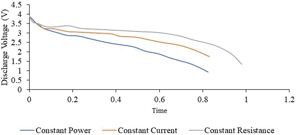
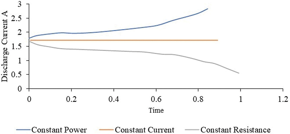
In the case of constant power discharge, the current increases as the voltage decreases to maintain constant power. In the constant current discharge, voltage decreases while current remains constant, and the power decreases. In the constant-resistance case, the current is decreasing to maintain constant resistance.
It was theorized that LCA is not applicable for battery systems under constant power modes because of the changing voltage of the battery. In a push for electrification, there were some hurdles to overcome, including system performance, range anxiety, charging time, and model correlation. These issues have prevented EVs from moving forward.
But there are other reasons for correlation issues, including our understanding of the power flow through the system, and the fact that the way components are currently tested does not reflect their real-world use case.
In a battery electric vehicle, the DC electrical power is generated by the battery pack. It is then converted to AC through the inverter and transmitted to the motor, as shown in Figure 3.
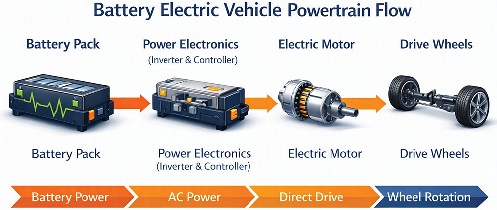
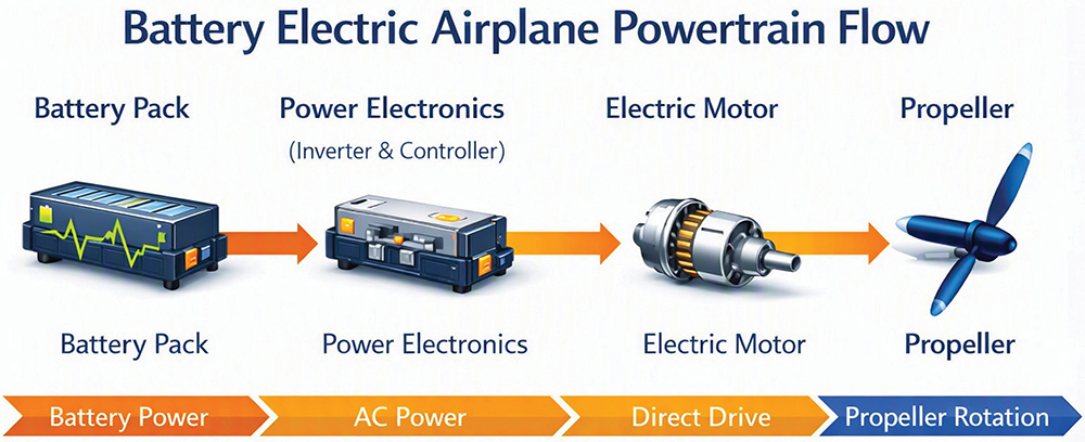
In general, the ground vehicle and the aviation vehicle will have the same power flow, but the motor will be different. Applying Kirchhoff’s Voltage Law (KVL) will not account for the power that must be delivered to the motor. To satisfy the power needed at the motor, the battery will use a constant power discharge.
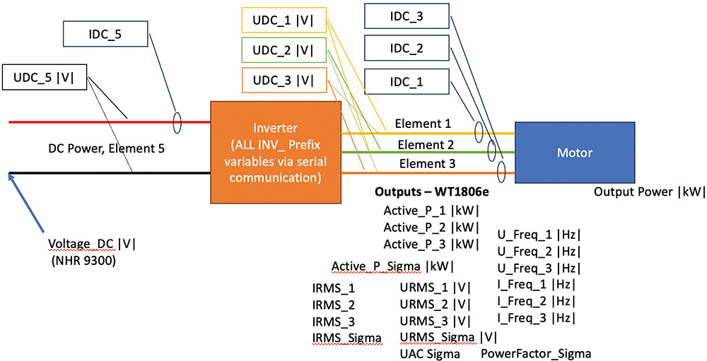
A Kia EV6 was tested at different input voltages, and the power to the wheels was fixed to force the power source to meet the power needs. An NHR 9300 battery test system was used to provide power, and a Cascadia Motion CM350DZ Motor Controller (inverter) was used.
The power flow was mapped out with the voltage and current measured out of the power source, the power in and out of the inverter, and the power out of the motor, as shown in Figure 5.
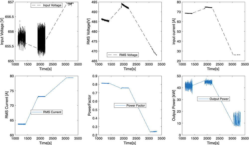
The first step was to examine the output of the DC power into the inverter, as shown in Figure 6.
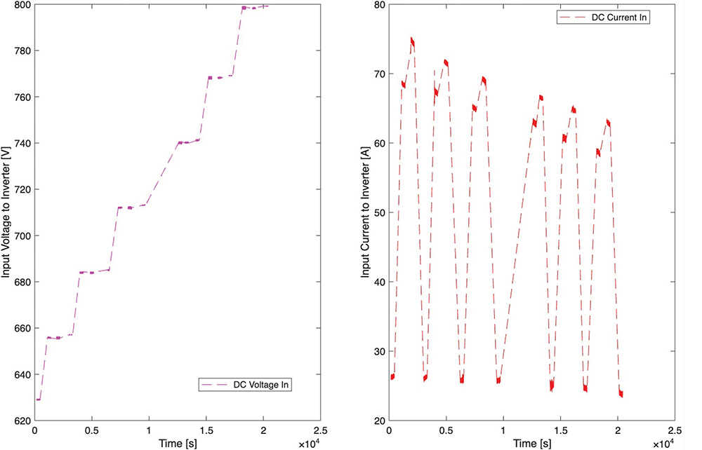
A detailed examination of each individual voltage is conducted. The inverter is requesting more current at a lower voltage to meet the power demands of the loads, and this increase in current will impact the sizing of the battery. If the voltage of the system were constant, then the current would be constant.
The output voltage and current of the inverter were further examined, as shown in Figure 7.
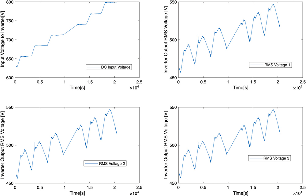
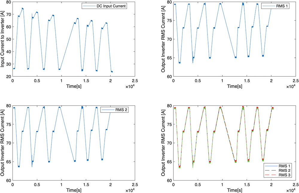
The clearer look shows the relationship between the input voltage and the output voltage of the inverter, as shown in Figure 9.

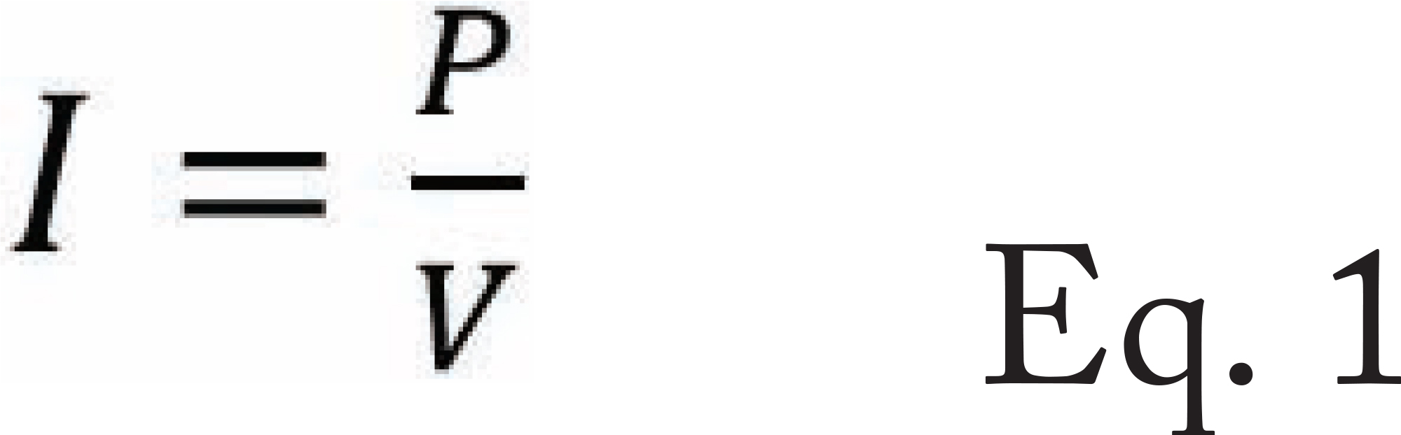
In the case of the constant power load, the current is dependent on the voltage, as shown in Equation 1.
The inverter is the bridge between the DC source and the load. When the voltage drops, the loads fight back and request more current.
The inverter output voltage is also dependent on the input voltage. The AC output voltage is a fraction of the input voltage, as shown in Equation 2.

The DC current did increase as the voltage decreased, and the output currents were not impacted by the change in input voltage.
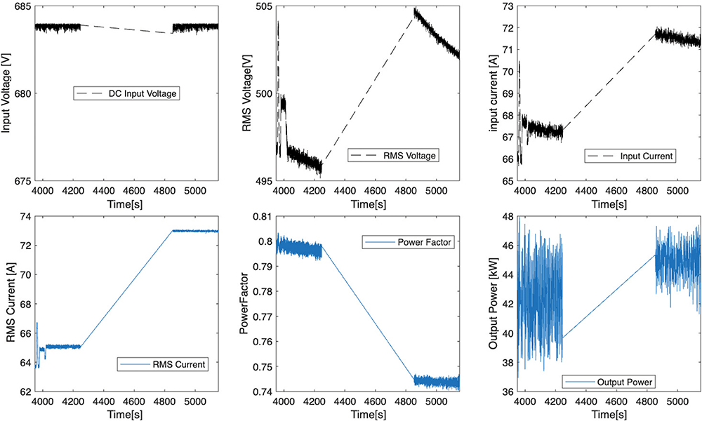
The same process was repeated for the second voltage case of 680‑685 V, as shown in Figure 11.
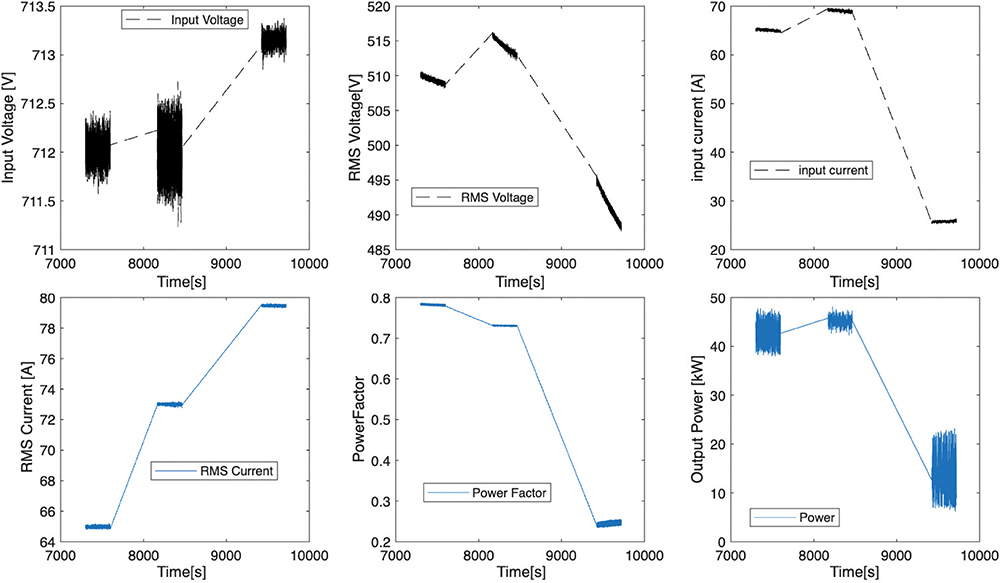
The next voltage case isolated is the 711-714 V case, and the results are shown in Figure 12.
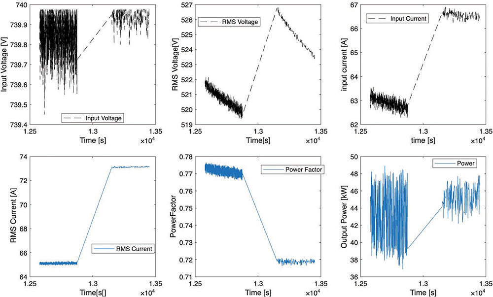
The parameters voltage, current, and power factor were also plotted for the 739-740 V case, as shown in Figure 13.
The next case examined is the 767-770 V case, and it is shown in Figure 14.
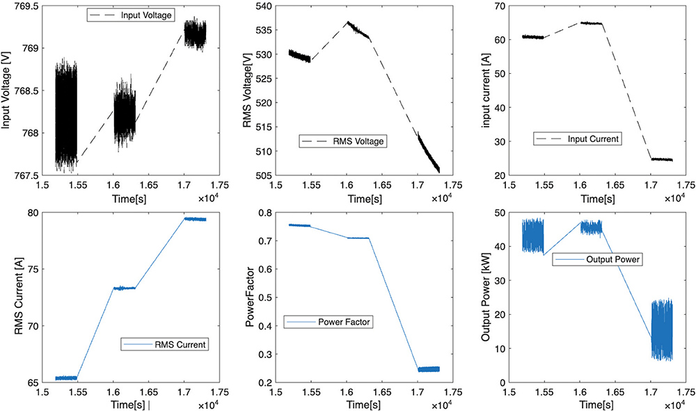
The power factor does range between 0.2 – 0.8.
The last case was performed at 798 V, and the voltage and currents are shown in Figure 15.
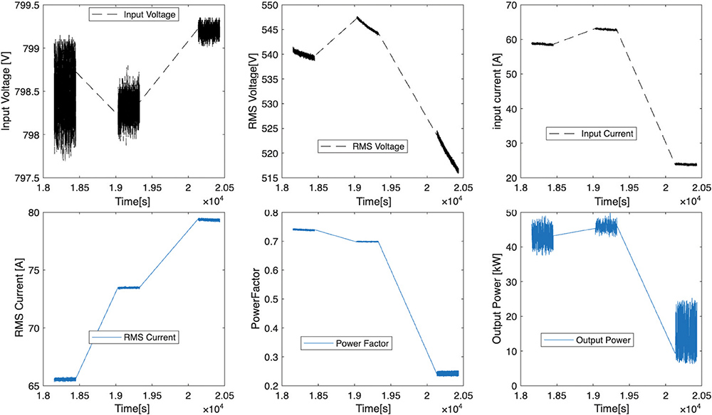
In each of the cases, the power at the wheels has been met to sustain vehicle speed. The output RMS voltage of the inverter ranges from 515‑545 V.
The data show that, as voltage decreases, the inverter must draw increasingly higher current to maintain mechanical power, raising apparent power, thermal loading, and stress on all downstream components.
This confirms that LCA is insufficient for battery‑powered constant‑power systems because it assumes fixed impedance and cannot capture the nonlinear, voltage‑dependent dynamics imposed by the battery. The presence of effective negative inductance demonstrates the need for co‑modeling the battery, inverter, and motor in the power domain, where voltage collapse, current rise, and power flow are treated as coupled phenomena.
Recognizing and modeling this behavior is essential for accurate system prediction, proper component sizing, and reliable thermal and electrical design in modern electrified powertrains.
Under the constant input voltage, the input current to the inverter increases. The input voltage to the inverter impacts the output voltage of the inverter. The output current of the inverter remained constant for all cases. The change in output voltage would indicate a different power output of the inverter.
The key reason that the electronics behave differently when powered by a battery is the changing input voltage. An ideal power source will provide a constant voltage and constant power. A battery does not have a constant resistance. Instead, its resistance changes with state of charge and current, making resistance matching more difficult to achieve. In the case of a fuel cell, it is a current-controlled voltage source (CCVS), and its resistance will be constant, and a steady state solution can be achieved if fuel is provided to the fuel cell.
We recommend that battery-only power systems be modeled together and not independently. A change in batteries will impact the system performance and system efficiency. Changes in batteries will impact the current and heat generation of the electrical components. A battery is not an independent power source; it is a dependent one. Electrical devices like inverters and motors need to be tested at different input voltages to better characterize them. And doing so will allow them to be properly modeled with the battery.
The different testing will also understand the current draw of each component, and can also be used to better estimate the heat generation. With a better understanding of the heat generation, the thermal system can be better designed to reduce the risk of components reaching their thermal limit.
Electronics need to be designed for either a constant input voltage or a variable input voltage range. The constant input voltage design would be suitable for hybrid power systems. But in battery electric vehicles, the voltage will change with time. The changing input voltage will influence the design of electrical components like inverters and motors. If the system has a constant input voltage, then the system needs to be designed differently.
I would also like to thank the Government’s support in the publication of any material based on or developed under this contract, as stated in the following terms:
(b) All material, except scientific articles or papers published in scientific journals, must, in addition to any notices or disclaimers by the Contractor, also contain the following disclaimer: Any opinions, findings, and conclusions or recommendations expressed in this material are those of the author(s) and do not necessarily reflect the views of the Air Force Research Laboratory/AFWERX.

Nicholas Ingarra is a Principal Engineer, technical consultant, and strategic advisor with more than 20 years of experience in advanced energy systems across the automotive, defense, and commercial sectors. He holds a Ph.D. and M.S. in Mechanical Engineering and is a licensed Professional Engineer specializing in electrochemical systems, thermodynamics, and system-level integration. He can be reached at nicholas.ingarra@sbcglobal.net.