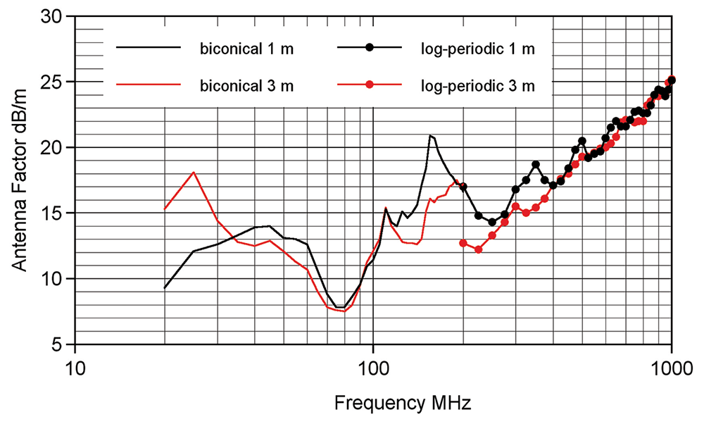
his is the third part of our article “(Re)Discovering the Lost Science of Near Field Measurements.” Part 1 of this article (see In Compliance Magazine, July 2023) explained what near and far field measurements entail, and that one-meter measurements are very much near field. Part 2 (In Compliance Magazine, August 2023) explained the evolution of the earlier 12” and present-day one-meter separation measurements, considerations in antenna selection, the difference between antenna-induced and field strength limits, and the evolution from one to the other. This third part investigates practical problems arising from the misapplication of field intensity and far-field concepts to near-field phenomena.
SAE ARP-958 uses the physical model of two identical antennas in each other’s far field (Friis equation) to calculate an “effective” gain at one-meter separation. This is an effective gain because the antennas are in each other’s extreme near field. Therefore, the antenna factor so derived is only valid for measuring the field at that distance, and the standard of value is that antenna’s response to its own field at that distance. There is no particular value to comparing the “field intensity” measured by (for example) a biconical to the field intensity that biconical would see from another biconical a meter away. In fact, it is quite harmful in that there is an unspoken (and incorrect) assumption on the part of many EMC engineers that the field intensity measured at one-meter separation is scalable in some prescribed manner so as to be able to predict what the measured field intensity would be at another distance.
Based on the diagram of Figure 9, the Friis equation may be written as:
PR/PT = GT GRλ2 / (4πr)2
The Friis equation assumes that the separation distance places the antennas in the far field. In that asymptotic condition, the gain values are independent of separation, which is what makes far-field antenna calibration useful. But two elementary observations are apparent:
- The left-hand side ratio is bounded by unity, and in practice will always be less than unity, or 0 dB; and
- The right-hand side increases without bound as the separation decreases unless the gain values decrease commensurately.
Assuming half-wave dipoles (far field gain = 1.64 numeric, 2.15 dBi), one may solve the Friis equation for the distance at which the left-hand side ratio is unity, or 0 dB.
r = 0.13λ, or
r = D/4
where D is the half-wave dipole length
The exact same effect is seen with higher gain antennas: gain derates rapidly from the far field values at separations less than a tenth of the far field distance (2D2/λ).27 Figure 12 is copied from Reference 27 and shows gain derating for both dish and horn aperture-type antennas. Figure 12 is used in the following manner.
The Reference 27 handbook citation is not the origin for this work. It goes back over sixty years and is hardly new.28
The fourth and final installment of this article will list theoretical misunderstandings arising from the erroneous substitution of field intensity for antenna-induced concepts and show the serious practical results of these theoretical mistakes.
Endnotes
- One prominent physicist refers to what the author terms the “extreme near field” as “inside the dipole.”
- A complete mathematical treatment may be found in a companion article in this magazine issue, entitled “Journey To The Center Of The Dipole.”
- https://www.ets-lindgren.com/products/antennas?page=Products-Landing-Page
- Schelkunoff, S.A. & Friis, H.T. Antennas, Theory and Practice, John Wiley & Sons, Inc. 1952.
- NAWCAD TP 8347, Electronic Warfare and Radar Systems Handbook, October 2013
- Hansen, R.C., and Bailin, L.L., “A New Method of Near Field Analysis,” IRE Transactions on Antennas and Propagation, December 1959.


