Filter Designs for Switched Power Converters: Part 2
Expert Insights
EMC Concepts Explained
Hot Topics in ESD

Filter Designs for Switched Power Converters: Part 2
Expert Insights
EMC Concepts Explained
Hot Topics in ESD

solid-state amplifiers


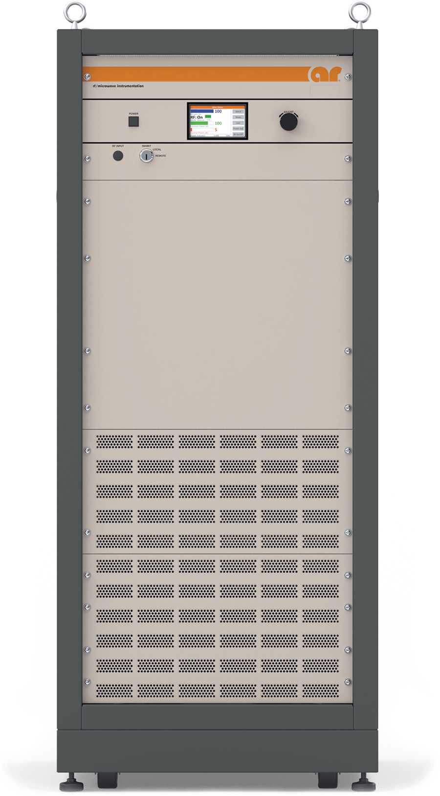
- HIRF (High-Intensity Radiated Field) Testing
- NEMP (Nuclear Electromagnetic Pulse) Testing
- EW (Electronic Warfare) Jamming and Jamming Simulation
- Component Testing
- EW (Electronic Warfare) Destruction
- Radar and radar simulation


ISSN 1948-8254 (print)
ISSN 1948-8262 (online)
is published by
Same Page Publishing Inc.
451 King Street, #458
Littleton, MA 01460
tel: (978) 486-4684
fax: (978) 486-4691
© Copyright 2025 Same Page Publishing, Inc. all rights reserved
Contents may not be reproduced in any form without the prior consent of the publisher. While every attempt is made to provide accurate information, neither the publisher nor the authors accept any liability for errors or omissions.
editor-in-chief
Please contact our circulation department at circulation@incompliancemag.com
According to a Public Notice issued by the Commission, Tesla is seeking a waiver of current UWB restrictions to implement a UWB optimal positioning system that would operate in the 7.5‑8.5 GHz frequency range to facilitate the wireless charging of its electric vehicles…
According to a press release, the Commission has issued infringement decisions to 27 individual Member States for failure to notify the Commission of their transposition efforts related to 11 different EU directives. The notices cover directives addressing the reporting of air pollutant…


ver the last several months, we showed how to use near-field probes to characterize and interpret dominant harmonic energy sources on PC boards and how to use RF current probes to characterize the coupling of these energy sources to power and I/O cables. This time, we’ll discuss how to use a nearby antenna to monitor actual emissions from a product or system.
While many designers attempt to perform radiated emissions troubleshooting at an outdoor site or in a semi-anechoic chamber using a third-party test lab facility, I’ve found a much more efficient method is to perform this using a nearby antenna right on your own work bench (Figure 1). Performing this testing in‑house also allows additional tools and resources to be close at hand.
Best of all, a calibrated EMI antenna is not really required, as all we care about are relative changes! In one case, I was testing an industrial printer and connected a 1m-long piece of wire to the spectrum analyzer and stretched it out nearby. I’ve even had clients use a nearby Wi-Fi antenna for troubleshooting. So long as you can see the harmonic emissions, you can try various mitigations and observe the results in real time!
ooking back at the 2024 IEEE International Symposium on EMC, the one concept that is still ringing in my ears is what is often called “ground” but is actually a power or signal return or reference plane. The reason is that what is commonly called “ground” and what is a power or signal return, or that of a reference plane, is not the same. There were several talks on this concept given by many people who are much brighter than I am and have proven to me they know what they are talking about. And yet, I recently read an article whose author seemed confused about what a ground was.
The concept of electrical “ground” has its basis in the “earth-return telegraph” and the first telephone connections. Signal lines were routed between two points, but the return path used was the ground, literally the earth. The earth is also used for electrical safety return paths, neutral reference, and split phase power reference. In the United States, the electrical power panel in the home or commercial locations (when correctly installed) have the neutral lines and safety grounds tied to a common bus bar, which should be routed to a ground rod near the power panel.
Part 2

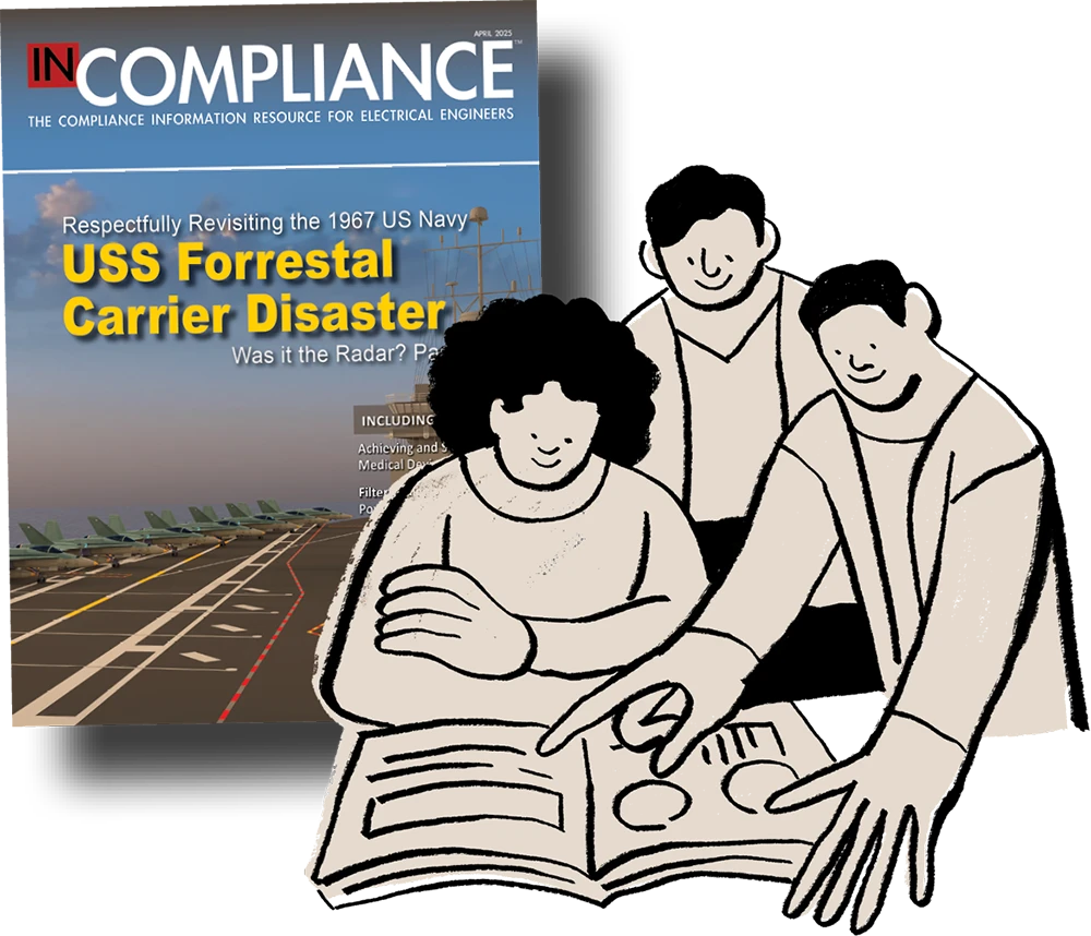
n 1967, while on patrol in the Gulf of Tonkin, the United States Navy Carrier USS Forrestal was executing wartime missions over North Vietnam. At 10:45 am local time, the ship was preparing to launch more than 27 A-4 Skyhawk and F-4B Phantom Fighter jets, all fully fueled and armed with a mixture of iron bombs, precision missiles, and Zuni rocket launchers. At 10:51 am, an F-4B experienced an un-commanded Zuni missile launch on the flight deck, striking a neighboring A-4 and starting a fire, causing a series of devastating secondary explosions. Quenching the fire nearly capsizes the ship, which is ultimately saved through the heroics of the sailors who served aboard the Forrestal.


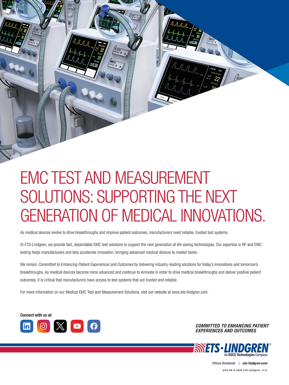
he journey of bringing a new medical device to market is littered with potential pitfalls and obstacles that need to be overcome. A common challenge facing innovators is how to navigate regulatory pathways. Typically, this is a topic that is low on people’s to-do lists.
Irrespective of the regulatory pathway that applies to your product, you will have to demonstrate that your product has valid scientific evidence of adequate safety, performance, and efficacy throughout its product lifecycle. Failure to provide this information is a common reason for delays and rejection of regulatory documentation by regulators such as the U.S. Food and Drug Administration (FDA) and conformity assessment bodies such as EU Notified Bodies. This often leads to increasing costs and failure to obtain market access of a device that may have a positive health outcome and better safety profile.
Therefore, taking time to evaluate regulatory pathways early in the development of a product will mean that you understand evidence requirements and minimize the likelihood of issues during regulatory approval processes. It will also mean that you have a better understanding of regulatory costs and timelines.
Once a positive regulatory decision has been made and your device is on the market, that is not the end of the journey. No medical device is infallible. So, plan to expect issues to arise. Each year, regulators such as the FDA and the United Kingdom’s Medicines and Healthcare Regulatory Agency (MHRA) receive thousands of adverse incident reports about medical devices each year. The harm or potential to cause harm to patients and users caused by device or manufacturing failure, user error, or new unidentified hazard can result in recalls, changes in design, further validation and verification, and reputational risk.
A product life cycle approach, underpinned by a proactive and reactive regulatory and compliance strategy, helps to ensure that you consider all of the key steps, from first having your idea to placing a medical device on the market and then maintaining that market access.


n Part 1 of this series of articles1, we provide an overview of EMI filter design for switch-mode power supplies (SMPS). In this part, we will examine specific aspects of switched power converters. The goal is to help readers understand:
- Emission spectrum of an SMPS
- Noise sources in a typical SMPS
- Coupling mechanisms of noise in an SMPS
- Grounding considerations in switched-mode power supplies and
- Input and output capacitors
his is the first of two articles devoted to the topic of inductor impedance evaluation from the S parameter measurements (capacitor impedance evaluation from the S parameter measurements was described in [1] and [2]). This article describes the impedance measurements and calculations from the S11 parameter using the one‑port shunt method, two-port shunt, and two‑port series methods. The next article will discuss impedance measurements and calculations using S21 parameters with two‑port shunt and two‑port series methods.


Read every issue online.
Stay ahead with expert blogs.
Access past issues anytime.
Find industry leaders and services.
White papers, guides & more.
Delivered straight to your inbox.

AC and DC Ionization, the Whole Story
lacing a target too close to an ionizer, whether AC or DC, may increase the risk of negative effects, such as localized charge buildup, electrical stress, or minor material degradation. To prevent adverse effects and potential damage, maintain an appropriate distance from the ionizer. While AC ionizers can generate higher electric fields than DC ionizers, their impact on the target must be considered in the context of the target’s impedance, size, and the ionizer’s operational frequencies. When these factors are accounted for, the potential risks posed by AC ionization to the target are not significantly greater.
The test sample in Figure 2a was designed to simulate the exposure of targeted devices and structures of various sizes. The experiment used four pads: a 1.0‑inch square, a 0.5-inch square, a 0.25-inch square, and a 0.018 x 0.057-inch rectangle. Each pad was connected to a Lecroy WaveSurfer 64Xs oscilloscope using a 10 MW (9.5 pF) probe. A Faraday Cage was used to shield the probes from the electric field and minimize measurement contamination.


You can do that here.
View Index
 Visit In Compliance’s booth at these events!
TCB Council Spring Workshop
April 6-8
EMCH2025 International Conference on Electromagnetic Compatibility
April 6-9
A2LA Annual Conference 2025
April 7-9
The Battery Show Middle East 2025
April 24
Cyber Security and The Cyber Resiliency Act
April 24-25
Principles of Electromagnetic Compatibility
April 28-May 2
EMA Expo
May 6
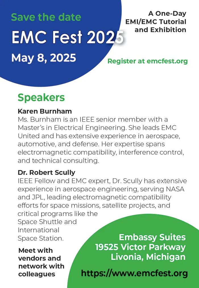
2025 Chicago IEEE EMC Mini Symposium
EMC Fest 2025
May 12-16
2025 International ESD Workshop (IEW‑Europe)
May 13-15
2025 IEEE International Symposium on Product Compliance Engineering (ISPCE)
May 18-21
2025 International Applied Computational Electromagnetics Society (ACES) Symposium
May 19-21
EMC & Compliance International Exhibition & Workshops
May 19-22
2025 IEEE International Instrumentation and Measurement Technology Conference
2025 Asia-Pacific International Symposium and Exhibition on Electromagnetic Compatibility (APEMC)
May 20
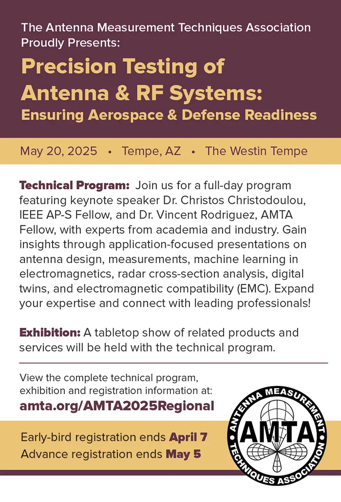
AMTA 2025 Regional Meeting
June 3-6
WPTCE 2025IEEE Wireless Power Technology Conference and Expo
June 15-20
IMS 2025 – IEEE International Microwave Symposium
June 26
Cybersecurity Maturity Model Certification for Federal Government Procurements