EMC Testing
A Rational Clarification
Product Liability Law and Its Effect on Product Safety
A Rational Clarification
Product Liability Law and Its Effect on Product Safety


Visit us at www.arworld.us or call 215-723-8181. Talk to an applications engineer at 800.933.8181.


ISSN 1948-8254 (print)
ISSN 1948-8262 (online)
is published by
Same Page Publishing Inc.
451 King Street, #458
Littleton, MA 01460
tel: (978) 486-4684
fax: (978) 486-4691
©Copyright 2023 Same Page Publishing, Inc. all rights reserved
Contents may not be reproduced in any form without the prior consent of the publisher.
While every attempt is made to provide accurate information, neither the publisher nor the authors accept any liability for errors or omissions.
publisher
bruce@brucearch.com
keith.armstrong@
cherryclough.com
Leo@EisnerSafety.com
dgerke@emiguru.com
ken.javor@emcompliance.com
kenrossesq@gmail.com
wernerschaefer@comcast.net
Subscriptions outside North America are $129 for 12 issues. The digital edition is free.
Please contact our circulation department at circulation@incompliancemag.com


The proposed rule changes were detailed in a Notice of Proposed Rulemaking issued by the Commission. In brief, the proposed changes would eliminate the current seven business day mandatory waiting period to issue notifications of a breach, and would also require notification of all reportable breaches to the FCC, the Federal Bureau of Investigation (FBI), and the U.S. Secret Service…
In an Order issued in late 2022, the FCC approved across-the-board increases of approximately 7-8% for most forfeiture penalties for violations of FCC rules and requirements. Under the 2015 Inflation Adjustment Act, federal agencies are required to annually adjust civil monetary penalties…

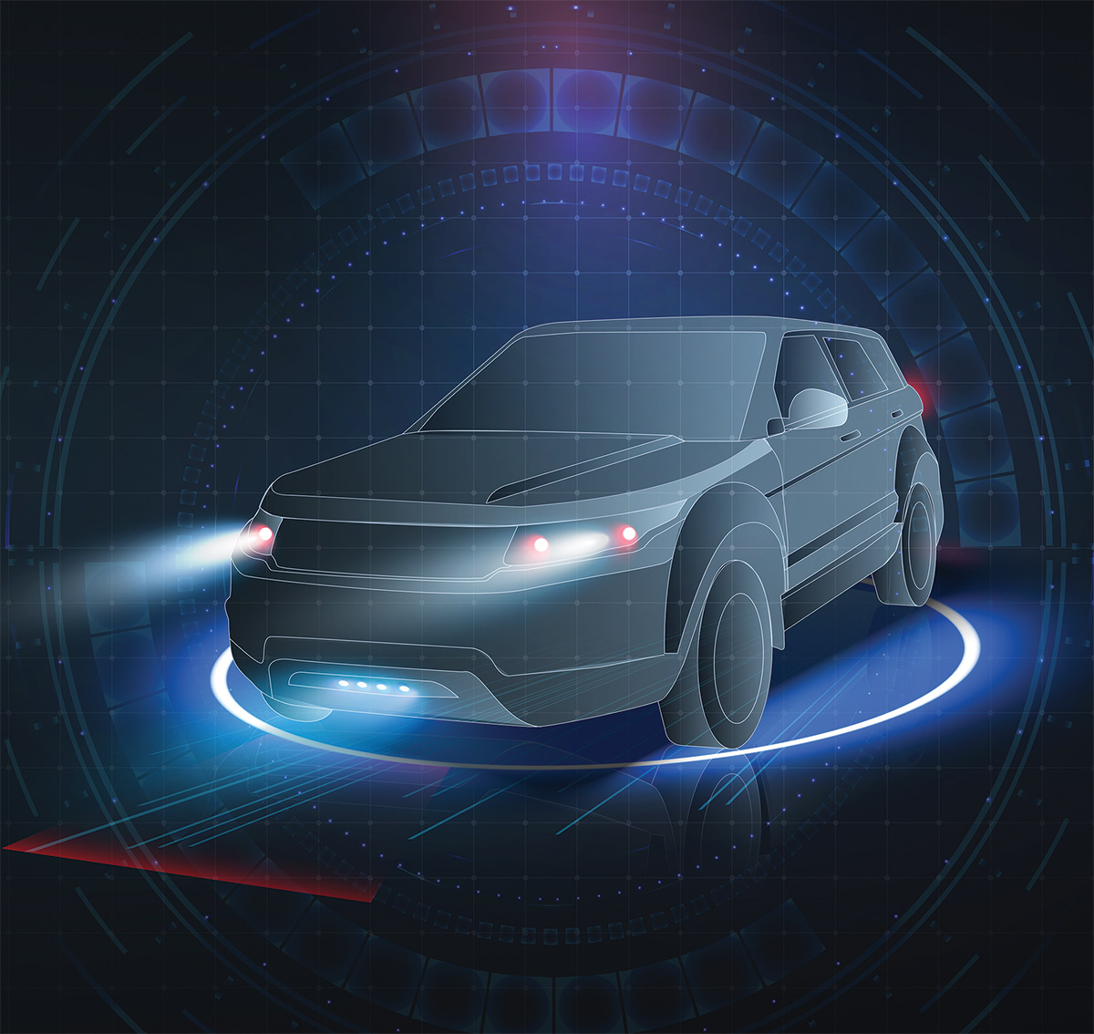
utomotive standards addressing electromagnetic compatibility (EMC) are developed mainly by CISPR, ISO, and SAE. CISPR and ISO are organizations that develop and maintain standards for use at the international level. SAE develops and maintains standards mainly for use in North America. In the past, SAE developed many EMC standards which were eventually submitted to CISPR and ISO for consideration as an international standard. As the SAE standards become international standards, the equivalent SAE standard is then withdrawn as a complete standard and reserved for use to document differences from the international standard.
Each vehicle manufacturer has internal corporate standards that specify the testing, severity, and sensitivity levels that components used in their vehicles, and the complete vehicle must meet. As with the government standards, these documents usually refer to the CISPR and ISO documents with differences in scope or test levels. In the past, a vehicle manufacturer based in the U.S. referenced SAE documents in their corporate standards, today most U.S.-based vehicle manufacturers market worldwide. Therefore, they reference CISPR and ISO standards in their internal corporate standard, and this is also true for other established and emerging manufacturers.


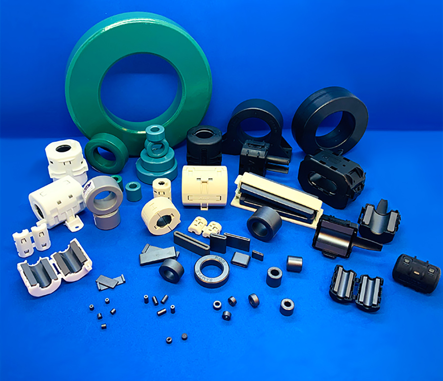

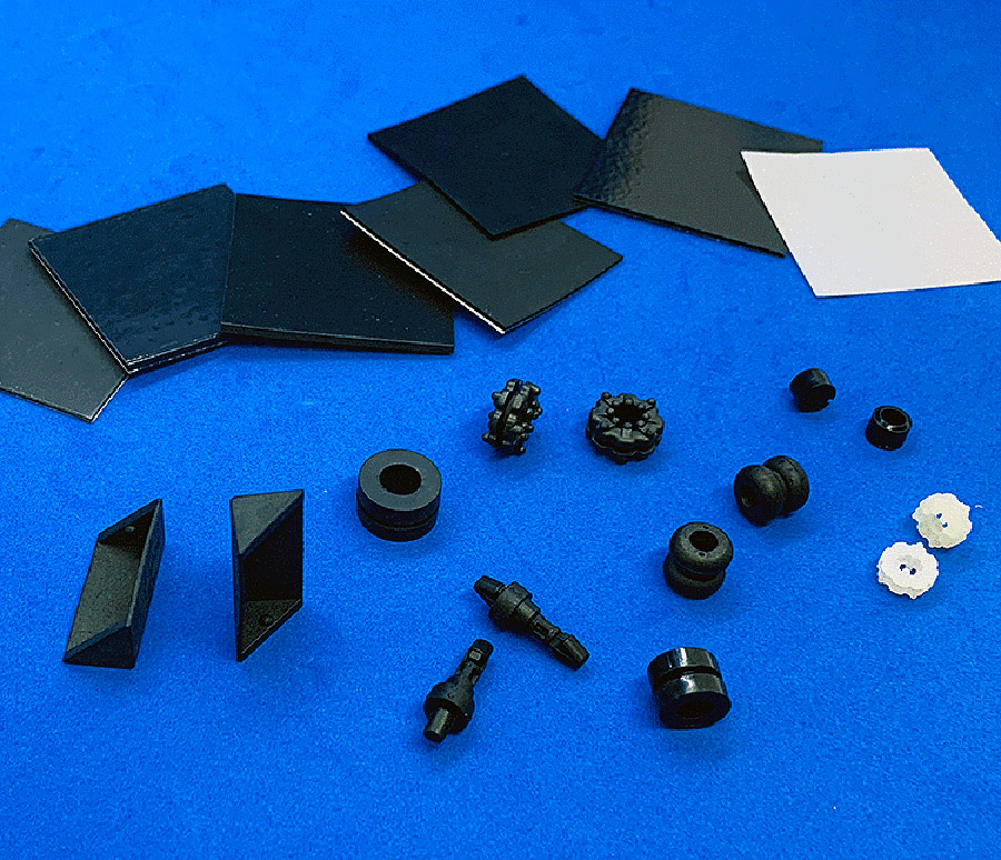
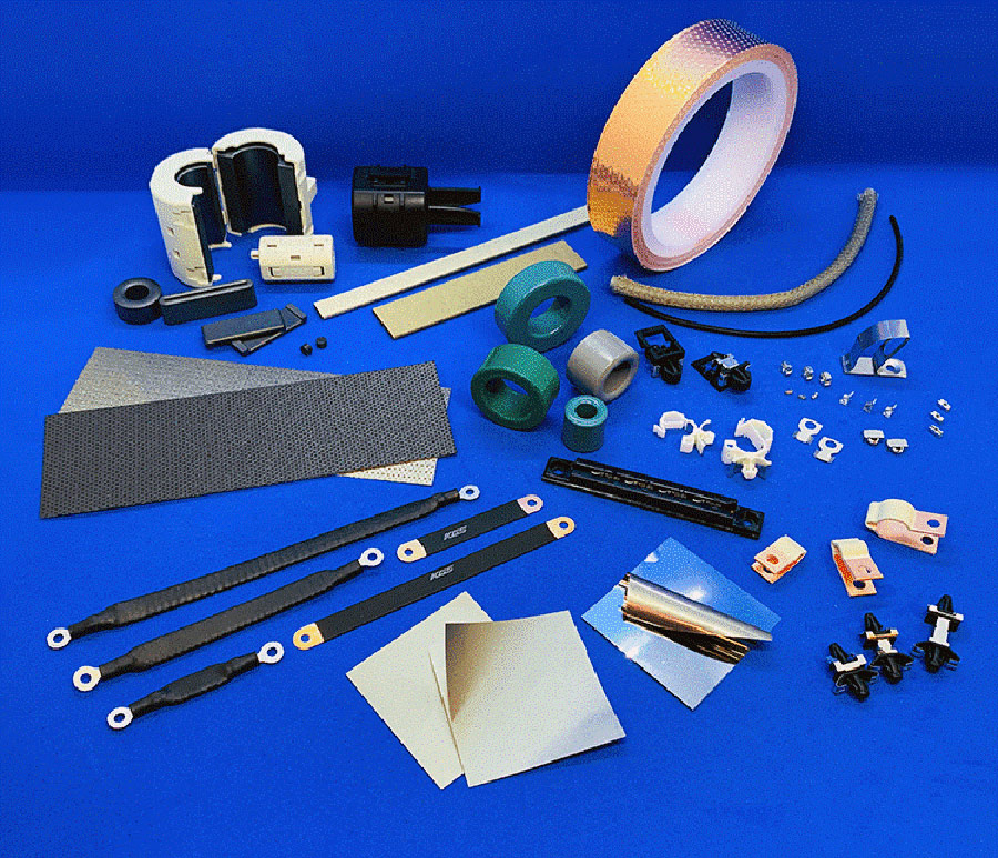
Grounding contacts, clamps, and straps
Ferrite cores
EMI absorbers
Silicone-free thermal pads
Dual-function (EMI + thermal)
Fan noise damper
Toll free (US only): 1-855-EMC-PART
International: +1-408-971-2055
Email: sales@kgs-ind.com

Feature Article
Evaluation of Intelligent and Non‑Static Power Sources: A Rational Clarification

Editor’s Note: The paper on which this article is based was originally presented at the 2021 IEEE International Symposium on Product Compliance Engineering (ISPCE), conducted virtually in September 2021. It is reprinted here with the gracious permission of the IEEE.
Copyright 2021, IEEE.
Introduction
Examples of these Intelligent or Non-Static Power Sources, include USB, Power over Ethernet (PoE), Reverse Power Feeding (RPF), and “intelligent fault managed” technologies. These technologies and Intelligent fault managed systems (sometimes called “Fault Managed Power Systems”) may include sources that sense a specified connection to some remote equipment and then turn on power, and/or, disconnects/reduces the voltage level when a fault condition is sensed. A sensed fault condition could include an abnormal load impedance or circuit, and/or a simulated human bridging.
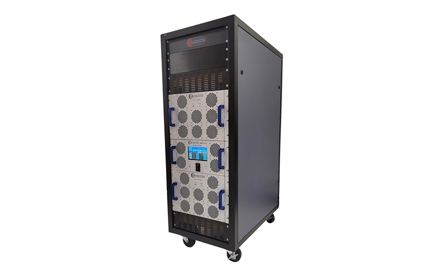
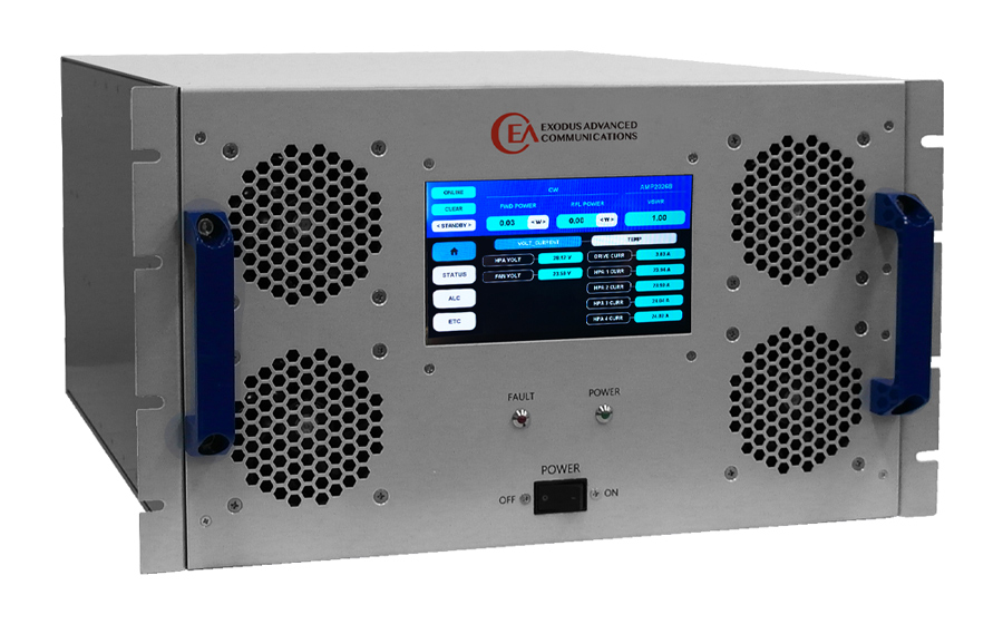
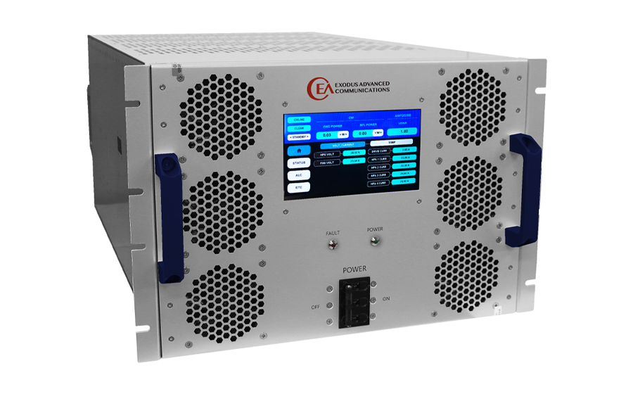
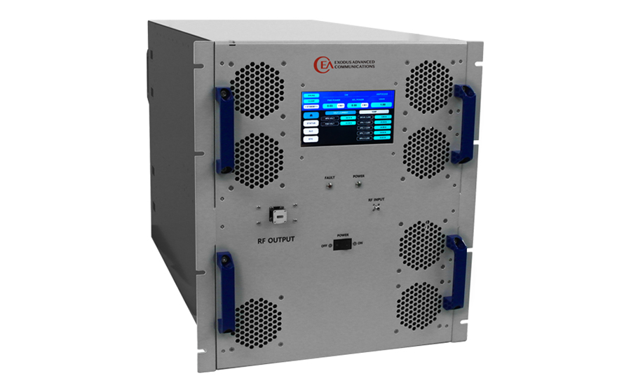


Tel: 1-702-534-6564
Fax: 1-702-441-7016
Email: sales@exoduscomm.com


roduct liability is one of the most important U.S. legal developments in the last 100 years. It has directly impacted consumers, product users, manufacturers, and others who produce and sell products, government regulators, insurance companies who insure the defendants in these claims and lawsuits, and, of course, lawyers for the plaintiffs and defendants. Product liability cases have bankrupted manufacturers and insurance companies, caused manufacturers to stop making and selling certain products, and created an entire industry of those who seek compensation for injuries and loss, those who seek to make money prosecuting or defending the parties in these claims and lawsuits and, finally, those who seek to make products safer.
The goal of any manufacturer is to prevent or minimize the possibility of incidents, ensure compliance with all applicable legal, safety, and technical requirements, and do what they can to make themselves and their products defensible in the event incidents or alleged non-compliances occur. To do that and to minimize or prevent liability, manufacturers need to understand the legal requirements, standards, and best practices so they can design, manufacture, and sell reasonably safe and compliant products, adequately monitor their products after their sale, and comply with any resulting post-sale regulatory requirements.

Sinusoidal Steady State Analysis of Transmission Lines
his is the second of the three tutorial articles devoted to the frequency-domain analysis of a lossless transmission line. In the previous article, [1], the general solution for the voltage and current in sinusoidal steady state was derived and the concept of the input impedance to the line was presented. This article shows numerous methods of calculating the voltage, current, and input impedance at various locations on the transmission line, using the Circuit Model 1, [1], described next.
Consider a lossless transmission line with the characteristic impedance Zc, driven by the source located at z = 0 and terminated by the load located at z = L, as shown in Figure 1. (This circuit was referred to as Circuit Model 1, in [1]).
The voltage and current at any location z away from the source were derived in [1] as
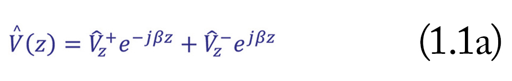
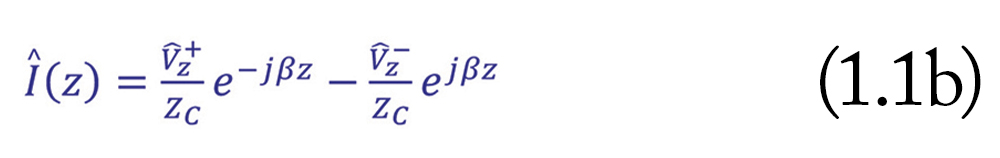
where β is the phase constant of the sinusoidal voltage source and the Vz+ and Vz– are yet to be determined constants.
Note: In [1] these constants were denoted as V+ and V-. Here, we use a different notation to distinguish between the constants for two different circuit models. Using Model 1, shown in Figure 1, we move from the source at z = 0 to the load at z = L, and use constants Vz+ and Vz–. In Model 2, discussed in the next article, we move from the load at d = 0 to the source at d = L, and use constants Vd+ and Vz–. These two sets of constants are different.
The solutions in Eqns. (1.1) consist of the forward- and backward-traveling waves. The forward-traveling voltage wave is described by
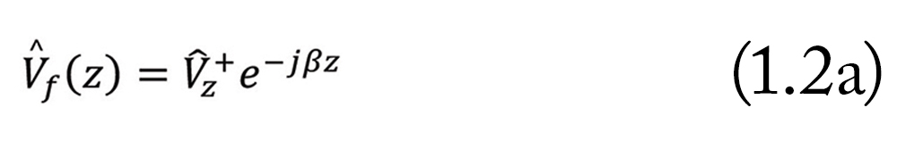
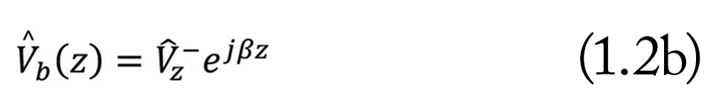
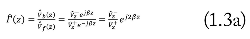
Using these two waves, we define the voltage reflection coefficient at any location z, as the ratio of the backward-propagating wave to the forward-propagating wave
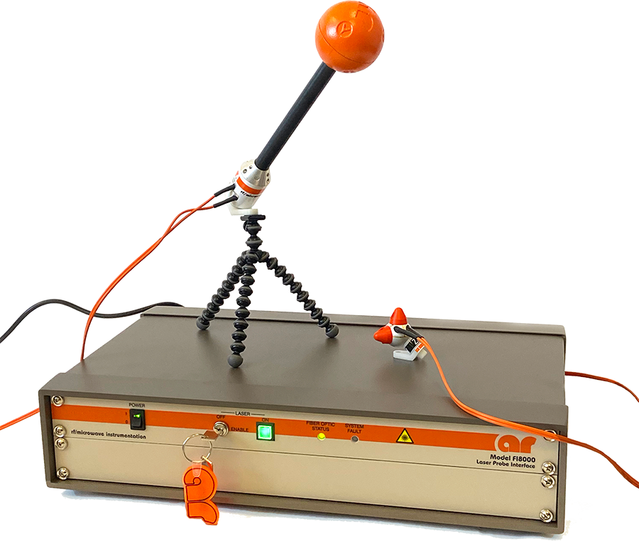
his article explores the waveform specifications called out in the IEC 61000-4-2 standard [1]. Verifying that a generator meets this specification requires specific equipment and conversion equations. The setup, data collection, and calculations required to validate equipment are explained here. Waveforms have been captured using the target called out in the standard, often called a Pelligrini target, for three different generator manufacturers and one pulser. These waveforms are analyzed in the time domain to verify the generators were within the standard’s specification. What comes as a surprise is the real waveforms. Waveforms from different generators look very different and it is surprising that they all pass the specification [2].
The spec limits are shown in Table 1. Note that the spec limits are quite wide; for instance, at the 30 ns and 60 ns current, the waveforms can vary by ±30%. The peak current can even vary by ±15%.
A Capacitively Coupled Pin Injection Method for Troubleshooting Immunity Issues
ulk current injection (BCI) tests are widely used for automotive, military, and aerospace EMC immunity tests. The test setup requires a high-power amplifier (often at least 80-watt unsaturated output power) and a BCI injection probe to achieve a reasonably high interference level on the device under test (DUT).
In one recent example, an automotive remote controller unit experienced immunity issues during the BCI test in an accredited EMC testing laboratory. The module’s local interconnect network (LIN) lost communication in the frequency range between 5 and 15 MHz.
The same failure mode must be reproduced in a pre-compliance EMC test setup to fix the issue. For pre-compliance EMC tests, producing the same failure mode often requires a different setup unless the specific BCI test equipment is available.
Some of the test setups often used in pre-compliance EMC immunity tests include:
- A workbench BCI test using an RF monitor current probe as an injection probe is described in [1];
- A homemade BCI probe method is described in [2];
- A coupling and decoupling network (CDN) method;
- A transverse electro-magnetic cell (TEM Cell) method.
A Fischer current monitor probe F-33-1 is often used as an injection probe for pre-compliance BCI testing [1]. The test setup was documented in detail in [3] and it was mentioned that, in order to achieve a higher level of RF interference, one would need to put some ferrite chokes on the other side of the probe to reflect more energy to the DUT.
At home.
on the go.


View Index
DesignCon 2023
February 28 – March 2
Fundamentals of Random Vibration and Shock Testing Training
March 20 – 24
EMC Designing for Compliance
March 23 – 31
17th European Conference on Antennas and Propogation (EUCAP)
2023 International Applied Computational Electromagnetics Society (ACES) Symposium
March 27 – 30
Military Standards 810 (MIL-STD 810) Test Training
March 27 – 31
EMC Designing for Compliance
March 28 – 30
EMV 2023
