for Installations
Firmware: The Inexpensive Way to Address EMC Issues
Safety Outside the Box: Going Beyond the Standard Specific to Your Equipment

Firmware: The Inexpensive Way to Address EMC Issues
Safety Outside the Box: Going Beyond the Standard Specific to Your Equipment


ISSN 1948-8254 (print)
ISSN 1948-8262 (online)
is published by
Same Page Publishing Inc.
451 King Street, #458
Littleton, MA 01460
tel: (978) 486-4684
fax: (978) 486-4691
©Copyright 2020 Same Page Publishing, Inc. all rights reserved
Contents may not be reproduced in any form without the prior consent of the publisher.
While every attempt is made to provide accurate information, neither the publisher nor the authors accept any liability for errors or omissions.
publisher
bruce@brucearch.com
keith.armstrong@
cherryclough.com
Leo@EisnerSafety.com
dgerke@emiguru.com
ken.javor@emcompliance.com
kenrossesq@gmail.com
wernerschaefer@comcast.net
Subscriptions outside North America are $129 for 12 issues. The digital edition is free.
Please contact our circulation department at circulation@incompliancemag.com
According to a Notice of Proposed Rulemaking (NPRM) published in the Federal Register, a “Made in the USA” claim can only be used in cases where “the final assembly or processing of the product occurs in the United States, all significant processing of the product occurs in the United States, and all or virtually all ingredients or components of the product are made and sourced in the United States.” The requirement applies to comparable claims for products using words including “manufactured,” “built,” “produced,” “created” or “crafted.”
Producers who promote or offer for sale products as “Made in the USA” that do not meet all of these conditions can be found to have engaged in unfair or deceptive practices under FTC regulations, and therefore subject to civil penalties.
According to a Memorandum of Understanding (MOU), the FCC, along with the U.S. Department of Health and Human Services (HHS) and the U.S. Department of Agriculture (USDA) will work together to develop and implement a joint Rural Telehealth Initiative intended to “address health disparity issues, resolve service provider challenges and promote broadband services and technology in rural areas of America.”
Under the terms of the MOU, the agencies have agreed to establish an interagency Rural Telehealth Initiative Task Force comprised of representatives from each agency and charged with developing a formal plan for the Initiative, consistent with the respective missions and authority of each partner agency. The Task Force will serve as a forum for the exchange of agency expertise, as well as relevant scientific and technical information, data and publications.

his article discusses the common-mode and differential-mode radiation from cables and presents the measurement results from the SMPS connecting wires.
If the fields generated by the forward current cancel the fields of the return current and no other circuits, or sources, or coupling paths are present, then the forward current equals the return current. In virtually any practical circuit, a different scenario takes place, as shown in Figure 2.
ÎD is referred to as the differential-mode (DM) current while ÎC is referred to as the common-mode (CM) current. The DM currents are usually the functional currents. They are equal in magnitude and of opposite directions. The CM (unwanted) currents are equal in magnitude and of the same direction (See [1] for the discussion of the CM current creation).
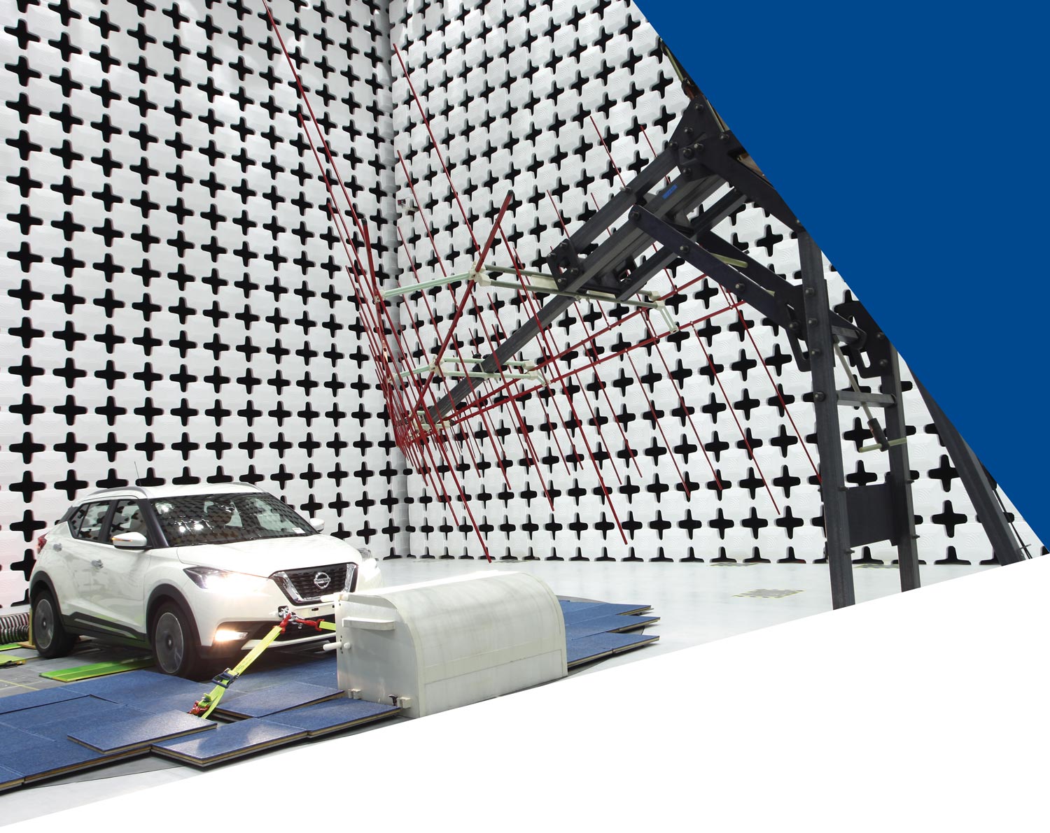
Enjoy performance and peace of mind in a single, high-performance solution. AR-supplied test chambers incorporate patented, inherently fire-retardant absorbers that release no carbon dust and carry no heavy, poisonous chemicals. They are RoHS and REACH compliant and manufactured in a facility certified according to ISO 9001:2015 and ISO 14001:2015 standards.
Backed by a 25-year performance warranty, these absorbers do not absorb humidity, which can alter performance characteristics over time and compromise measurement accuracy.
Our test chamber design also minimizes the risk of exposing operators to high-power electromagnetic fields leaking out of the chamber. This benefit is derived from our pan-type RF shielding construction instead of the traditional wood-core construction, which over time can swell and degrade shielding performance.
To find out more about the safest choice in chambers and absorbers, call us at 215-723-8181, or visit www.arworld.us/Chambers.
Other ar divisions: modular rf • sunar rf motion • ar europe
Copyright © 2020 AR. The orange stripe on AR products is Reg. U.S. Pat. & TM. Off.
Other ar divisions: modular rf • sunar rf motion • ar europe
Copyright © 2020 AR. The orange stripe on AR products is Reg. U.S. Pat. & TM. Off.
or 2020, TSMC is targeting to start mass production of its first 5 nm technology. Also, at this node FinFETs are the transistor architecture of choice. In this article, we will introduce FinFETs and their advantages over planar transistors. We will discuss some of the ESD protection design challenges when designing in a FinFET technology and give an outlook on the successors of FinFET.

Several instances have been noted in ground-based applications where EMI emissions from commercial digital processing equipment have interfered with the operation of sensitive radio receivers. Of particular concern are radiated emissions from processor…
Currently there are numerous incidences of co-site, intra-ship, and inter-ship interference, as well as interference with the civilian community. For example, the Honolulu Airport air traffic control radars have been degraded by shipboard radars…
A maintenance person was working inside a fuel tank and experienced an arc from his wrench when removing bolts. It was found that maintenance personnel were routinely taking foam mats into the tank to lie on while performing maintenance…
To protect personnel on the ground from receiving electrical shocks, it is standard practice for rotorcraft to touch the ground with the hook before it is connected to the cargo. As the cargo is lifted, the whole system (aircraft and cargo) will become…
his summer, the International Organization for Standardization’s Technical Committee in charge of standards for safety signs and symbols, ISO/TC 145, published a new Technical Specification, ISO/TS 20559 Graphical symbols – Safety colours and safety signs – Guidance for the development and use of a safety signing system.1 This new international specification focuses on workplace safety sign systems. Yet many of its underlying concepts speak to various forms of safety communication meant to reduce risk in today’s world – including product safety labeling. In this article, we again go behind-the-scenes with insight from Geoffrey Peckham, the chairman of ISO/TC 145 and long-time member of the ANSI Z535 committee (as well as the founder of Clarion Safety Systems and the original author of this “On Your Mark” column).
According to ISO/TS 20559’s scope, it provides “recommendations and explanations on the practical application of safety signs to form a system of communication intended to reduce risk.” Safety signs and labels are basic communication tools used by organizations to lessen risk – but their risk reduction benefits are only fully achieved when these communication tools are designed correctly from the beginning, or, if already installed, replaced by signs and labels that meet the latest best practice industry standards. The new ISO technical specification, ISO/TS 20559, thoroughly describes the visual components that make up best practice “systems” of signage, making it an essential document for organizations to use to better manage risk.

As the quantity and variety of electronic equipment used in systems and installations continues to grow, EMC is becoming an increasingly important issue. Almost all my work on systems and installations since 1990 has been involved with items of equipment interfering with the correct operation of other items on the same site.
In 1990, variable speed motor drives using insulated gate bipolar transistors (IGBTs) and power field-effect transistors (PowerFETs) for high-speed power switching were very new, as were private mobile radio systems, and they both caused many problems with legacy electronic equipment. Since then, EMC standards and regulations in most countries have considerably improved the emissions and immunity of equipment, but at the same time, variable speed motor drives have constantly improved – by switching faster. Faster switching makes them more efficient, smaller and less costly, with the result that they are being used much more widely. Unfortunately, switching faster causes increased noise emissions at higher frequencies, increasing the possibilities for interfering with other equipment (see Figure 1).
STANDARDS OF EMC COMPLIANCY.
As an international manufacturer of market-leading components and systems that measure, shield and control electromagnetic and acoustic energy, ETS-Lindgren is the driving force that allows some of the biggest industry names, and latest technological advances, to meet compliance standards. From chambers to test cells, absorbers, positioners and antennas, ETS-Lindgren’s EMC solutions are designed for reliability, diversity, scale and precision.
More importantly, our ability to create real-world test scenarios, troubleshoot potential failures and maximize the chance of passing standards within the allotted time and budget; helps our customers bring life-changing products to market – faster.
To view our accreditations and case studies, visit our website at ets-lindgren.com.

he last thirty years have seen great strides in the deployment of communication network infrastructure. That growth is primarily due to the establishment of the IP protocol as a stable specification in the late 1970s. There have been many benefits to using an IP-based approach, and today all manner of different communications networks rely on its widespread adoption. That said, with an increasing emphasis on power-efficient communication for a growing variety of applications, there is a rising awareness that an alternative to IP might need investigation.
Since its formation, the TCP/IP protocol suite is responsible for creating the heart of the internet. The transport control protocol (TCP) deals with the transportation of data, the process of dividing up messages into packets and then reassembling them after transmission. The internet protocol (IP) takes care of the addressing and routing of the packets transmitted across a communications network of attached devices.
The TCP/IP protocol suite has seen many iterations to its specification over the years. Still, one of the guiding principles from its conception was that the endpoints occupied fixed positions and that their connections would remain unchanged. Increasingly, the networks in place today see that endpoints do move, and connections may be dropped and re-established depending on several criteria.

n more than ten years working in labs as an EMC engineer, the majority of devices and systems I have tested include two important elements that interact with each other, thereby allowing the equipment under test to work. Electronic boards and firmware. It is difficult to imagine an electronic board without firmware running in a microcontroller. Even a simple wall charger for batteries has integrated firmware to switch the behavior of the charger from constant voltage to constant current, and to switch into trickle charging or to begin the discharge process.
Over the years, I’ve come to think of firmware as the soul of every electronics board since, without firmware, almost every PCB would be “dead.” But because firmware is now so deeply embedded into the working mode of a device, what is the influence, if any, on a device’s EMC performances? Could, in theory, at least, a device using different firmware versions behave differently during EMC measurements? We’ll explore that question in this article.

Editor’s Note: The paper on which this article is based was originally presented at the 2018 IEEE International Symposium on Product Safety Engineering in San Jose, CA. It is reprinted here with the gracious permission of the IEEE. Copyright 2020 IEEE.
ou have designed your product and need to go through the testing, declarations and certifications to market it in your target countries and regions. You look through the harmonized standards in the Official Journal of the European Union that the Low Voltage Directive 2014/35/EU [1] calls out for presumption of conformity. You also contact safety agencies in other countries and regions where your product will be sold and get determinations of required standards and certifications.
Is it enough? Most likely it is not. Technology and entertainment products are pervasive in the home and, while parents are expected to protect their child, supervision may not always prevent or minimize significant injury. In today’s litigious society, you have done the bare minimum if you have followed the steps in the previous paragraph. Plaintiff’s attorneys will be more than glad to point out that you did the minimum required.
Designers and compliance engineers must do their due diligence and look beyond the base standards and minimum requirements. This paper will not give you every possible scenario to consider in the design and use of your product, but it is the author’s intention to get you to think “outside the box” of the minimum requirements with some basic due diligence and risk assessment methodologies.
Resource
Guide
MacArthur Compliance Services, LLC.
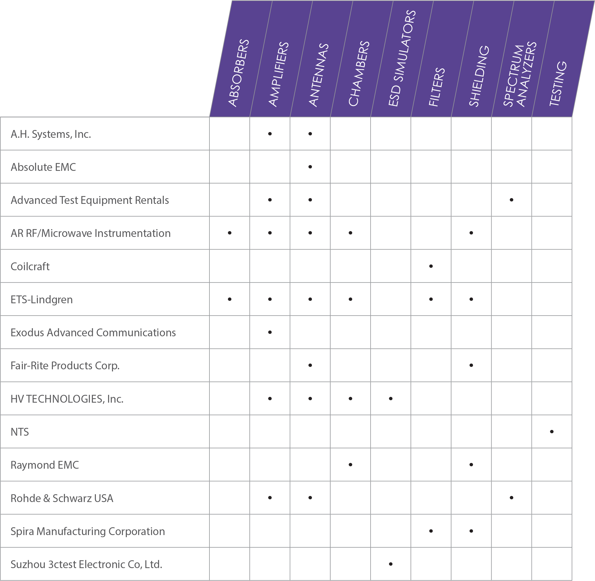
The process of making informed purchasing decisions can be quite complex. From absorbers to testing, today’s compliance engineer must be knowledgeable and well-versed in what to look for when selecting products and services that will work best for your needs.
This is where the Product Resource Guide comes in. In this year’s Guide, we highlight eight product categories—offer guidance on the use of these products—and selection tips on how to choose the right product or service for your applications.
So, whether you’re simply looking to replace an old piece of equipment, or are fully outfitting a brand-new lab, the Product Resource Guide is here to help.
We hope you’ll find the 2021 Product Resource Guide an invaluable resource that you keep handy year ‘round.

Materials
ou understand how RF absorber works, appreciate why its pyramidal shape influences performance, can describe how it’s specified for performance, know how to select the correct length and shape for your application, and understand how it is manufactured and how the manufacturing process affects absorber quality. These are all great attributes of RF absorber that you must take into consideration when properly outfitting an anechoic chamber for EMC testing purposes. But have you also considered safety attributes, including the maximum power handling capability the absorber will need to meet in your application and also its flammability rating? The safety performance specifications of RF absorbers are just as important as the other attributes of RF absorber performance. Let’s talk about them next.
- Know how anechoic absorber works. Absorber is designed to reduce reflections from impinging electromagnetic (EM) waves, and “absorb” incident EM energy.
- Match absorber design to application. Absorber works by dissipating the EM energy inside the absorber and turning it into heat. In most RF, microwave and antenna applications, the lossy dielectric works best because of superior EM absorption at higher frequencies.
- Pyramidal shape influences absorber performance. Broadband absorbers work by avoiding “sudden” changes in impedance for the impinging wave and gradually terminate and absorb the EM wave.
- Specify absorber for RF performance. Absorber is specified for reflectivity as a function of frequency at normal incident angle. Understand that reflectivity degrades at larger incident angles
- Match absorber length and shape for your application. Pyramidal absorber length determines how well it can work at the lowest frequencies.
- Use commonly available absorber lengths. Save money, speed delivery by choosing absorber in typical, off the shelf lengths.
- Determine maximum power handling capability of absorber. Polyurethane absorbers are specified to withstand a maximum power of W/in2 of continuous wave (CW) incident field under room temperature with no additional forced airflow.
- Manufacturing process impacts absorber quality. Find a computer controlled manufacturing process that begins with homogeneous blocks of polyurethane foam.
- Use non-hygroscopic absorber. Maintain a stable absorber electrical property and RF reflectivity by reducing moisture, which affects electrical conductivity significantly.
- Confirm RF performance verification testing. Ask how your supplier tests the absorber to verify performance reflectivity before shipment. Is each piece of absorber tested or sample tested one piece per batch? Is each piece serialized? Ask these questions protect your investment!
sk any experienced EMC test engineer or technician what one of the most frequently asked questions they get is and they’ll probably tell you something along the lines of the following:
“With the current broadband RF amplifier and antenna combination we have, what’s the highest field strength obtainable?”
The requestor is usually trying to find equipment that generates some enormously high field strength level to test their product, probably already knowing beforehand that the existing amplifier/antenna combo is not suitable.
The main reason the antenna/amplifier combo chosen is probably not adequate is because we usually only purchase what we need at the time. More power costs more money when it comes to broadband power amplifiers, so we typically only specify/buy to meet our current needs rather than what we may need in the future. This is a common cost-limiting approach practiced in most EMC test facilities.
- Determine the Frequency range of operation needed, sometimes more than one amplifier is required.
- Determine if you need a Pulse or CW type of Amplifier. Example: HIRF EMC applications require High Power Pulse Amplifiers.
- Determine the minimum power needed from the amplifier. Example: As you go up in frequency, antenna gain improves, so a lower power amplifier may be acceptable.
- Assess the system losses between the amplifier and the Antenna/DUT. Example: If the test setup has 6dB of losses, then the Amplifier power needs to be 6dBm higher.
- Some modulations, if required for the test application, would require a higher power amplifier. Example: When performing an 80% AM modulation test, the amplifier needs to have 5.1dBm of margin to accommodate the peak.
- Antennas, Cables, DUTs & Rooms have cumulative VSWR. It is best to allocate for some power margin.
- Consider the application, is this a single test or will it be used repetitively.
- Consider your desired RF connection types and locations optimal for your application.
- Also consider if automation will be used so the appropriate remote capability is included.
A balun transformer is used in antennas for matching the wideband impedance of the antenna to that of the amplifier. It is often the balun that determines the maximum amount of power that can be delivered to an antenna used for EMC testing purposes. Balun equipped antennas can also be used for radiated emissions testing.
Bilog antennas (ironically also portmanteau for biconical/log-periodic – BI-LOG) or just a plain biconical or plain log-periodic antenna must be protected against accidental damage during EMC compliance testing. A balun transformer, located at the antenna’s feed-point, limits the power-handling ability of the antenna because some of the power delivered to the antenna ends up as heat in the core and windings.


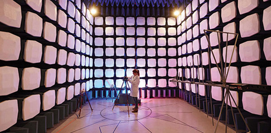
f you’re technically-minded and involved in EMC testing, then you’re probably well aware of all of the nerdy things involved in running an EMC test facility, properly outfitted with the best semi-anechoic chamber(s) and associated test equipment and cabling. To the exact letter of the law (i.e., standard), you already know how to set up and perform an accurate and repeatable radiated emissions or RF immunity scan. You know how ferrite tile and RF absorber works and which antenna(s) work best for each particular type of EMC test. You’re an expert at EMC testing but, when it comes to installing, tearing down, and moving an EMC chamber, you may not have a clear understanding of all of the non-engineering tasks that go along with such an important event.
- Selection of a chamber is determined by the standard being tested to. Some types of EMC Chambers are: Commercial, MIL STD/DO-160, CISPR 25 and Reverb.
- Commercial chambers are used for IEC and CISPR standards for Emissions and Immunity testing. Typically, “Semi – Anechoic” and achieve CISPR16 (Emissions) and IEC 61000-4-3 (Immunity) chamber performance requirements.
- Semi-Anechoic Chambers are strategically lined with absorber and ferrite to meet specifications without fully lining all surfaces.
- Verification for CISPR 16 compliance is Normalized Site Attenuation (NSA) (26 MHz-1 GHz) and Site Voltage Standing Wave Ratio (sVSWR) (1-40 GHz). This verifies the chamber “Quiet Zone”. Quiet zones are normally equal to the turntable diameter. EUTs can’t be larger than the quiet zone.
- For compliance, variations in the quiet zone performance cannot exceed +/-4db for NSA and 6dB for sVSWR.
- Verification for IEC 61000-4-3 is a field uniformity test. Typically, a 1.5m x 1.5m vertical plane consisting of 16 points spaced 0.5 m apart is the measured area. At least 12 Points must vary by <6dB.
- MIL STD and DO-160 chambers can be Semi-Anechoic or Fully Anechoic. Standards require the absorber have a minimum absorption of 6dB from 80MHz to 250MHz and 10dB above 250Mhz. A table with a conductive top is bonded to the shield ground is used for testing the EUT.
- CISPR 25 chambers are fully lined on walls and ceiling, contain a similar table with metal lining on top, and must pass the Long Wire Test or the Reference Site Method test to meet the Standard.
- Reverb chambers rely upon the reflectivity of the walls and an internal movable paddle to reflect generated signals and increase the value of V/m generated from the transmit antenna.
- Information needed to design a reverb chamber is the lowest frequency, the test volume, maximum V/m, and standard to be tested to (MIL STD, DO, ISO).
Simulators
more thorough “in-between calibration cycle” check of the ESD simulator’s output waveform is something every EMC engineer and technician should consider.
n previous articles (references 1 and 2), we covered the basics of EMI filters and some of the common reasons why they often fail to provide the insertion loss performance we expect from them.
We learned that the most common reason why filters fail, (besides bad coupling paths and cable routing around the filter, improper bonding and grounding, and non-ideal placement within the equipment) is that EMI filters are, more often than not, specified using 50Ω termination impedances on both the line and load sides during the insertion loss measurement.
The 50Ω/50Ω filter insertion loss measurement method is easy to perform because most RF measurement apparatus (connectors, cables, receivers, etc.) are built around a characteristic impedance of 50Ω. However, we know that filter performance is highly dependent on termination impedance and that real-life circuits rarely contain such ideal 50Ω impedances. Therefore, the 50Ω insertion loss test method cannot be relied upon to accurately predict filter performance once installed in actual equipment.
- Filters should perform in both symmetric and asymmetric mode. That is, they should remove differential and common-mode noise. Some manufacturers offer comparatively smaller filters, but only specify asymmetric performance. These fail to remove differential noise.
- Filters should be rated for the appropriate maximum Line-to-Ground or Line-to-Line voltage for a 3 phase system. This eliminates the uncertainty of whether a filter will work at circuit voltages lower than the maximum filter rating.
- Filters should be rated for the appropriate circuit current and be able to withstand an overload of 140% for at least 15 minutes. This ensures the survival of the filter under overload conditions.
- Filters should be rated for low temperature rise in order to increase their durability and reliability.
- Power filters should be listed by a Nationally Recognized Testing Laboratory (e.g. UL, Intertek). This ensures that a 3rd party has approved the safety of the filters.
- When testing for avionics at 400Hz power, filters should also use Power Factor Correction Coils. This ensures that high reactive currents at 400Hz are neutralized.
- Larger power filters (above 200 Amps) should have an option to be floor standing. This ensures that most of the weight is on the stand rather than on the shielded wall.
- Protection performance for HEMP/EMP filters should be according to MIL-STD-188-125 or IEC 61000-4-24. These are the preeminent standards used today for specifying conducted Point of Entry protection.
- When protecting a facility against HEMP/EMP, it is crucial to indicate if the filters will be installed inside or outside the protective shield. Only one side of the filter has the protective elements;the protection side must be that which is exposed to the threat.
- When using electronic power sources connected to filters, the source should have a transformer in its output circuitry. This minimizes unwanted interaction with filters.
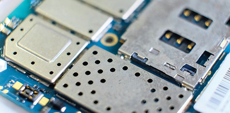
his article assumes the reader already has a basic understanding of how electromagnetic compatibility (EMC) shielding works. If you would like a refresher on EMC shielding, please see references 1 and 2, which describe how EMC shielding works in basic terms.
If you’re an electrical engineer and consider proper EMC shielding a mechanical only issue, please reconsider your position and keep reading.
Analyzers
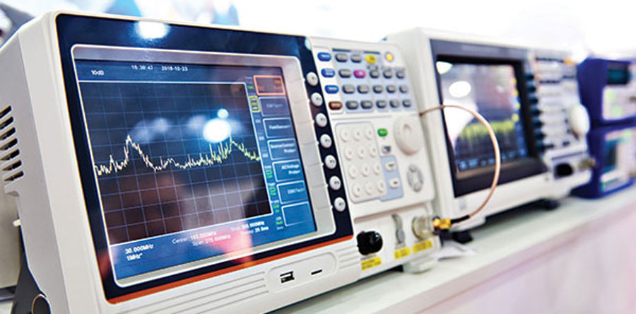
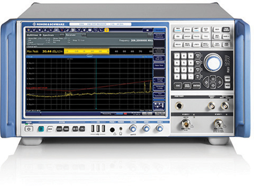
f you’re performing commercial radiated and conducted emissions measurements strictly by the book, you will want to utilize a measurement receiver or spectrum analyzer that fully complies with CISPR 16-1-1. Briefly, this is what this means:
Note 1: The specifications in CISPR 16-1-1 apply to EMI receivers and spectrum analyzers. The term “measuring receiver” is also used in the EMC community and refers to both EMI receivers and spectrum analyzers.
Note 2: Often, the receiver specification under question depends on the frequency range of operation. In CISPR 16-1-1, there is one receiver specification covering the frequency range 9 kHz to 150 kHz (Band A), one covering 150 kHz to 30 MHz (Band B), one covering 30 MHz to 300 MHz (Band C), and finally one covering 300 MHz to 1,000 MHz (Band D). This article covers the 9 kHz to 1 GHz frequency range of operation and Bands A through D. Band E covers the 1 to 18 GHz frequency range of operation and has its own unique requirements.
Note 3: Specific requirements for measuring receivers used for military testing are found in MIL‑STD-461G and DEF STAN 59-411.
Laboratories
or some manufacturers, the cost of outfitting an entire full-compliance EMC test facility is not justified. These entities do not have enough sales volume, build unique one-off units, have tight margins, or lack the resources to staff an entire on-site, full-compliance test facility.
These types of manufacturers must rely heavily on the services of out-of-house, third-party test laboratories to properly test their products to confirm compliance before placing their devices on the market. The major problem with this approach, however, is that should the product fail at the test lab, the result will be delayed product shipments and missed revenue opportunities.
Utilizing early-stage in-house pre-compliance testing and sound engineering judgment, along with pre-compliance test data will boost confidence that the product will pass when it is eventually sent out-of-house for full compliance certification work. Learning in-house, using pre-compliance test methods as early as possible (when first prototypes are available), instead of at the end of the product development program (when attempting certification tests at the full-compliance test facility) will inevitably save manufacturers time and money. During final certification testing, there is immense pressure to meet your production release deadlines and being charged big dollars for lab time by the hour adds a whole other layer to that pressure. Having a product fail at this point in the process could be fatal to the project, especially if competitors get their product to market ahead of yours.
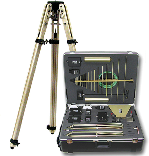
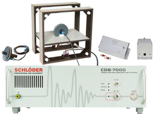
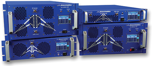
The AR Bargain Corner offers high-quality trade-ins, demos and discontinued models, many with the warranties still included. Shop now!
http://www.arworld.us/bargain-corner

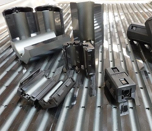
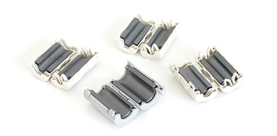
- Very effective at frequencies below 30MHz
- Highly polished edges produce results comparable to a solid core
- Available in a wide variety of sizes to fit most signal carrying cables
Fair-Rite Products designs and manufactures ferrite cores in many sizes and shapes in order to achieve EM compliance at frequencies from 100KHz to 1GHz. Call us today!

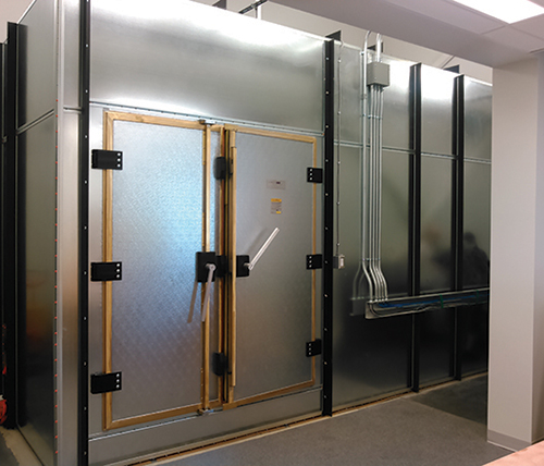
International Shielding Expert George Kunkel discovered a critical error: the accepted theory of electromagnetic shielding violates the basic laws of physics. This new book, the result of over 50 years of research, provides a more accurate, efficient way for design engineers to apply electromagnetic theory in the shielding of electrical and electronic equipment. Learn more at http://www.spira-emi.com.
View Index
MIL-STD-810G: Understanding, Planning and Performing Climatic and Dynamic Testing
October 6-7
Advanced PCB Design for EMC & SI
October 6-8
ETS-University: Automotive Course
October 12-14
ESD Auditor Certification Course
October 15
SCIP Database Solution
October 20-21
ETS-University: TILE! Software
October 27-29
Applying Practical EMI Design & Troubleshooting Techniques
November 2-5
Antenna Measurement Techniques Association (AMTA) 2020
MIL-STD-810G: Understanding, Planning and Performing Climatic and Dynamic Testing
November 10
Ground Resistance Training Seminar
November 10-12
EMC Fundamentals
November 16-17
IEEE SPCE 2020
November 16-18
Advanced PCB Design for EMC & SI and Mechanical Design for EMC
November 16-18
Sensors Expo & Conference


