In Compliance: The Compliance Information Resource for Electrical Engineers logo
Application of Thrifty Test Equipment for EMC Testing
Low-Cost Instruments and Procedures to Troubleshoot EMC Issues
PLUS
Introduction to Validation Test Concepts in a Mixed Signal ASIC

EMC Design Techniques for Electric Vehicle DC-DC Converters

hand reaching for digital tool option
PLUS
Introduction to Validation Test Concepts in a Mixed Signal ASIC

EMC Design Techniques for Electric Vehicle DC-DC Converters

December 2021
down arrow
Superiority
can only begin
with Ingenuity…
10kHz-51GHz Amps LNA’s, CW, Pulse Low to High Power
amps
… we are redefining
Ingenuity!
a world apart!
Commercial - Military - EMC typography
Exodus Advanced Communications logo
3674 E. Sunset Road, Suite 100
Las Vegas, Nevada 89120
Tel: 702-534-6564
Web: www.exoduscomm.com • Email: sales@exoduscomm.com
3674 E. Sunset Road, Suite 100
Las Vegas, Nevada 89120
Tel: 702-534-6564
Web: www.exoduscomm.com
Email: sales@exoduscomm.com
December 2021
Volume 13 l Number 12
Contents
Low-Cost Instruments and Procedures to Troubleshoot EMC Issues
By Arnold Nielsen
EMC testing laboratories often have limitations (limited availability, lead times, etc.) that can make it difficult to obtain timely results from routine troubleshooting. Inexpensive test equipment can support efficient and economical in-house EMC troubleshooting.
By Christopher Semanson
Traditionally, validation engineers of analog products have had to worry about one thing, their analog function. But with the advent of functional safety, the complexity in system design has increased, and functions once found only in digital devices are now making their way into analog devices as well. This leaves individuals with one question- how to validate?
Three Important Design Aspects You Must Get Right Before Designing a Converter
By Dr. Min Zhang
DC-DC converters are among the most important modules in an electric vehicle. In this article, we offer three recommendations to address design aspects of DC-DC converters that will make a huge difference in their EMC performance.
gold dollar symbol connected to gold electrical parts
electric mechanical board parts
frame of a car with a gold light behind it
In Compliance logo
In Compliance Magazine
ISSN 1948-8254 (print)
ISSN 1948-8262 (online)
is published by

Same Page Publishing Inc.
451 King Street, #458
Littleton, MA 01460
tel: (978) 486-4684
fax: (978) 486-4691

©Copyright 2021 Same Page Publishing, Inc. all rights reserved

Contents may not be reproduced in any form without the prior consent of the publisher.
While every attempt is made to provide accurate information, neither the publisher nor the authors accept any liability for errors or omissions.

editor/
publisher
Lorie Nichols
lorie.nichols@incompliancemag.com
(978) 873-7777
business development director
Sharon Smith
sharon.smith@incompliancemag.com
(978) 873-7722
production director
Erin C. Feeney
erin.feeney@incompliancemag.com
(978) 873-7756
marketing director
Ashleigh O’Connor
ashleigh.oconnor@incompliancemag.com
(978) 873-7788
circulation director
Alexis Evangelous
alexis.evangelous@incompliancemag.com
(978) 486-4684
features editor
William von Achen
bill.vonachen@incompliancemag.com
(978) 486-4684
senior contributors
Bruce Archambeault
bruce@brucearch.com
Leonard Eisner
Leo@EisnerSafety.com
Daryl Gerke
dgerke@emiguru.com
columns contributors
EMC Concepts Explained
Bogdan Adamczyk
adamczyb@gvsu.edu
Hot Topics in ESD
EOS/ESD Association, Inc
info@esda.org
advertising
For information about advertising contact Sharon Smith at sharon.smith@incompliancemag.com.
subscriptions
In Compliance Magazine subscriptions are free to qualified subscribers in North America.
Subscriptions outside North America are $129 for 12 issues. The digital edition is free.
Please contact our circulation department at circulation@incompliancemag.com
The EERC logo
Visit incompliancemag.com/EERC to access your free resources today!
Associated Research application note advertisement

Safe Workstation Best Practices


application note provided by

Associated Research logo
A.H. Systems White Paper advertisement

VSWR Explained


white paper provided by

A.H. Systems, Inc. logo
compliance news
New Solder Composition Could Extend Life of EV Electronics
A group of international researchers has reportedly developed a new formula for solder that could help to reduce cracking and premature wear in vulnerable electronics used in electric vehicles (EV).

According to a recent posting to the website of The Engineer, the new solder mix replaces common, lead-free replacements for lead that are more prone to degrade in the high-temperature environment found in EVs. Instead of using tin…

EU Task Force Offers Clarification of Surveillance Requirements for Legacy Medical Devices
A European Union (EU) task force has issued a document intended to clarify the application of the EU’s Medical Device Regulation (2017/745, also known as the MDR) post-market surveillance requirements to legacy medical products.

Published by the Medical Device Coordination Group (MDCG), the document, MDCG 2021-25 is intended to provide a “legally defendable and pragmatic” position on requirements…

Dilbert Comic Strip
DILBERT © 2021 Scott Adams. Used By permission of ANDREWS MCMEEL SYNDICATION. All rights reserved.
Feature Article
Application of Thrifty Test Equipment for EMC Testing
Low-Cost Instruments and Procedures to Troubleshoot EMC Issues
By Arnold Nielsen
gold dollar symbol connected to gold electrical parts
I

ssues related to electromagnetic compatibility (EMC) are often identified during qualification testing in an accredited EMC test lab which typically occurs late in the product design cycle. Obtaining a cost-effective solution to these EMC issues may be time-consuming, and many EMC labs can be fully booked or have limited availability, have long lead times, or involve significant costs. But inexpensive test equipment and procedures (let’s call them thrifty methods) used for helping to solve these EMC issues outside an EMC lab are very desirable, especially if no in-house EMC facilities are readily available.

There are several excellent resources for troubleshooting methods and building a low-cost EMC toolkit.1 This article offers some other test equipment options that have different capabilities and which can be even less costly. Although the thrifty method is mainly used to compare results before and after implementing a fix (not meeting a specification limit), with some experience, it can also be used in the pre-qualification development stage early in the design cycle to identify potential issues before formal lab testing. Identifying issues early allows maximum flexibility to experiment and provides sufficient time to make cost-effective changes before a design is frozen and difficult to change.

AR logo
AR logo
AR logo
We’re with you all the way
The broadest bandwidth with the highest power.
AR offers over 100 amplifiers ranging from 10 Hz – 50 GHz and with power levels of 1 W – 100 kW.
For more information on AR Amplifiers, visit www.arworld.us
AR Amplifier
Testing and Product Approvals for Global Markets
Happy Holidays
Stay Warm! in a speech bubble
Washington Laboratories, Ltd. logo
Stay Warm! in a speech bubble
Happy Holidays
Washington Laboratories, Ltd. logo
EMC/Wireless – Environmental – Product Safety
Washington Laboratories, Ltd. | 301-216-1500 | www.wll.com | info@wll.com
Washington Laboratories, Ltd.

301-216-1500

www.wll.com

info@wll.com
Feature Article
Introduction to Validation Test Concepts in a Mixed Signal ASIC
Adopting tried and true digital verification techniques to the validation of a mixed-signal power management device
By Christopher Semanson
Validation Test Concepts
H

ang around embedded software engineers long enough and the words design for test or test-driven development will become commonplace. This is because in a world where functionality is ever-increasing in complexity, you need to be able to both verify and validate your device’s functionality such that it matches the requirements. And, while these design practices are well understood in digital systems made up of microcontrollers (MCUs) or system-on-chip devices (SoC) with functional safety driving extremely distributed systems, they are just as applicable in low level mixed-signal devices.

Gone are the days where the main MCU of the embedded module is trusted to do everything; in industrial and automotive systems where safety is critical, there now exist other devices to help test the main microcontroller to aid in the safety integrity level (SIL) of the device. These functions vary in complexity and range from helping the MCU toggle pins to ensure stuck at faults are mitigated, to helping verify complex question and answer watchdog issues, and voltage monitoring functionality.

Often the next smartest device in the system is either another low-level MCU or, in the quest to simplify a bill of material (BOM), a power management device (a PMIC) with dedicated safety functions. And since these devices don’t have flash memory and are traditionally analog in nature, it makes the validation of these devices somewhat challenging for engineers who traditionally focus mostly on transient load responses.

To aid in helping an engineer develop a test philosophy for such a device, we will focus on a distributed system made up of both MCU and PMIC. The article will use this system to demonstrate validation concepts that system designers have been employing for quite some time, the simplest of which is an open loop test philosophy and its strengths and weaknesses. The closed or in-the-loop based test philosophy will address those weaknesses and demonstrate how one can easily expand upon their test setup by including an MCU to model the system or system device. Taking these two test philosophies together will shed light on how exactly a design-for-test philosophy can be adopted for a traditional analog-based device such as a PMIC.

ETS-Lindgren machinery
BEYOND MEASURE.™
ETS Lindgen logo
ETS Lindgen logo
Visit us, follow us, watch us, and connect with us at:

Facebook logoTwitter logoYoutube logoLinkedin logo

Visit us, follow us, watch us, and connect with us at:

Facebook logoTwitter logoYoutube logoLinkedin logo

ETS-Lindgren's EMC Testing Video
Going beyond the standards of EMC compliancy.

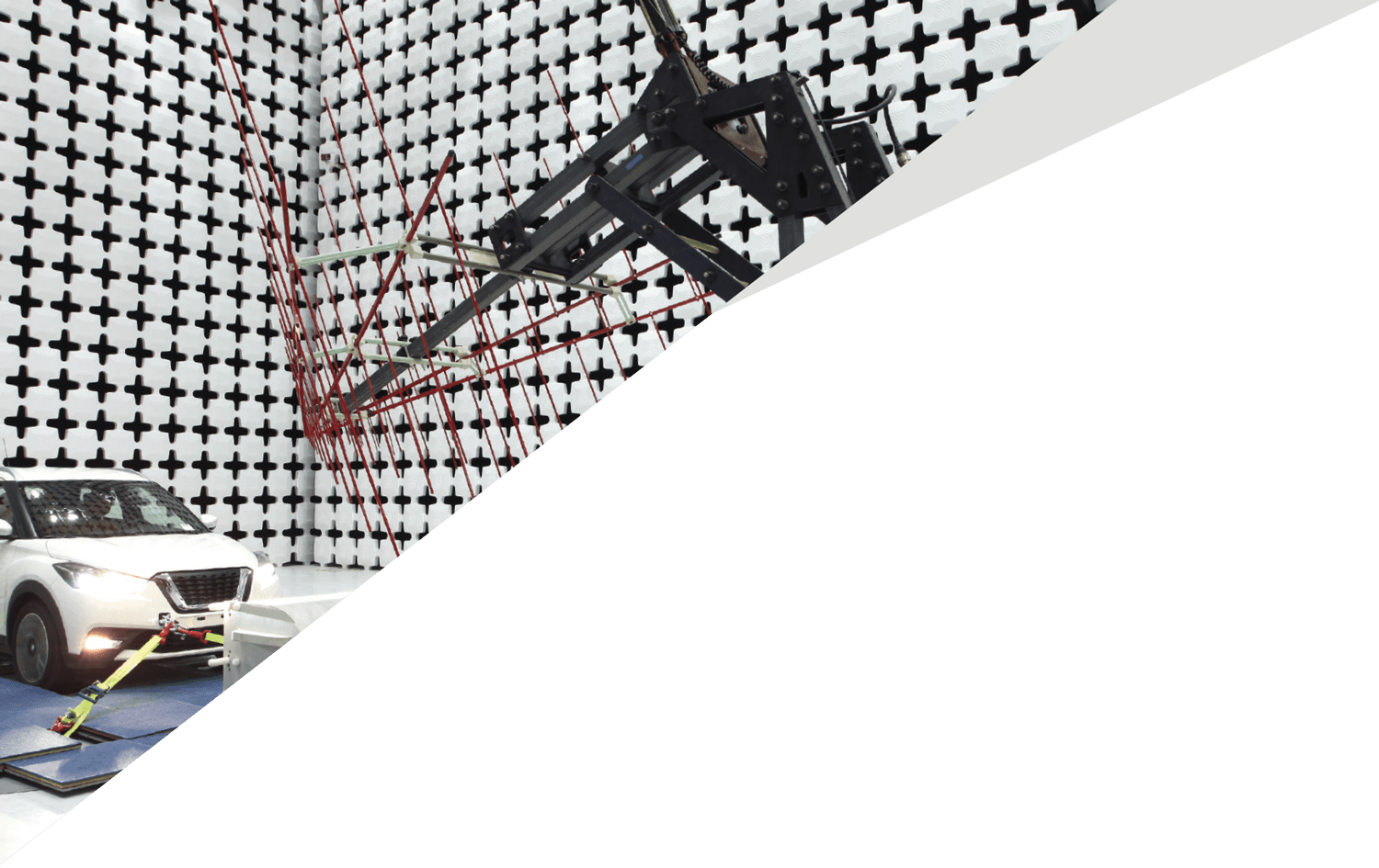
The future is here! From driverless vehicles to pizza-delivering drones to ear buds that act as virtual mixing boards for real-world audio, our lives are increasingly dominated by EMC. So, too, is ETS-Lindgren’s work in compliance testing and measurement, transcending the standards of EMC performance – Beyond Measure.

As an international manufacturer of market-leading components and systems that measure, shield, and control electromagnetic and acoustic energy, ETS-Lindgren is the driving force allowing some of the biggest industry names, and latest technological advances, to meet compliance standards. From chambers to test cells, absorbers, positioners, antennas, and software, ETS-Lindgren’s EMC solutions are designed for reliability, diversity, scale, and precision.

More importantly, our ability to create real-world test scenarios, troubleshoot potential failures, and maximize the chance of passing standards within the allotted time and budget helps our customers bring life-changing products to market – faster.

For more information on our EMC solutions, visit our website at http://www.ets-lindgren.com/industries/emc-testing.

Feature Article
EMC Design Techniques for Electric Vehicle DC-DC Converters
Three Important Design Aspects You Must Get Right Before Designing a Converter
Dr. Min Zhang
EMC Design Techniques for Electric Vehicle DC-DC Converters
W

hen helping clients in the automotive industry with their DC-DC converters to meet the stringent automotive EMC standards, I often find problems that share some common mistakes. For a start, 90% of the EMI issues are associated with a grounding issue. Poor DC link design contributes to poor conducted and radiated emissions. Another commonly seen mistake is a bad choice of switching devices, which often requires adding more filters later in the design process, significantly increasing costs and potentially jeopardizing the project.

When it comes to designing an electromagnetic (EM) compliant product, some planning is crucial to help ensure product performance and keep costs under control. In this article, we offer three recommendations addressing design aspects of DC-DC converters that will make a huge difference in their EMC performance.

The Role of DC-DC Converters in Electric Vehicles

If powertrain modules determine the performance of an electric vehicle (EV) [1], DC-DC converters then play an important role in the stability and reliability of an EV. Their primary function is to transfer energy from a source (e.g., battery pack) to systems and devices that consume that energy (all electronics loads, particularly in the low voltage distribution network of a vehicle). Because of this, the safety and functional safety aspects of a DC-DC converter are also critical. Redundancy design can also be seen for fault tolerance purposes.

EMC concepts explained
Evaluation of EMC Emissions and Ground Techniques on 1- and 2-layer PCBs with Power Converters
Part 7: AC/DC Converter Design with EMC Considerations
By Bogdan Adamczyk, Scott Mee, and Nick Koeller
T

his is the seventh column in a series devoted to the design, test, and EMC emissions evaluation of 1- and 2-layer PCBs that contain AC/DC and/or DC/DC converters and employ different ground techniques [1-6].

Figure 1 shows the functional blocks of the PCB assembly [1].
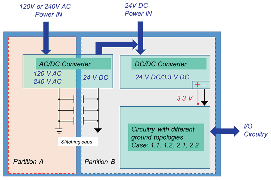
Top-level schematic – functional blocks
Figure 1: Top-level schematic – functional blocks
This column is devoted to the design of the AC/DC Off-Line Flyback Converter. We present a schematic and PCB layout along with the EMC considerations and supporting design documentation.
hot topics in ESD
Use of HBM and CDM Layout Simulation Tools
By Dolphin Abessolo-Bidzo for EOS/ESD Association, Inc.
Why is the Use of these ESD Layout Simulation Tools Necessary?
Electronic Design Automation (EDA) ESD verification tools have become instrumental to the design and verification flow of integrated circuits (ICs). This trend has been mostly driven by the extraordinary development and increasing complexity/technology scaling of ICs in the past few years. Furthermore, increasingly demanding product performance with necessary ESD reliability requirements makes it very challenging to achieve first-time-right silicon for both functional and ESD performance. In that context, the use of ESD verification tools to derisk IC designs before tape-out or for debugging purposes has become critical. In this article, the methodology of the state of the art of HBM and CDM layout simulations tools is described. Two real-life case studies are presented briefly, and the outlook towards future developments is discussed.
Methodology of the ESD Simulation Tools
The simulations are typically performed at top-level IC design. Figure 1 describes a simplified simulation flow of the HBM and CDM layout check tools. The design input used is a post-LVS (layout versus schematic) database. In addition, the ESD device characteristics are required and integrated as piecewise linear (PWL) or SPICE models. Also, technology files containing process information related to devices layers and metallization stack, typically from the process development kit (PDK) are included in the simulation setup. Finally, the backend ESD current density rules, gate oxide, and drain-source breakdown voltage stress are added as inputs to the ESD solver. Note that both ESD and victim devices characteristics are determined by means of transmission line pulse (TLP) and/or very fast (VF)-TLP characterizations. The main outputs from the ESD simulator are the ESD current density, gate stress limit violations, drain-source stress violations, and the overall ESD zaps results.
Engineering
EVENTS
calendar
In Compliance logo
In Compliance logo
Engineering
EVENTS
calendar
For a schedule of upcoming technical conferences and educational learning events aimed specifically at electrical engineering disciplines, visit us online:

https://incompliancemag.com/events

In Compliance: The Compliance information Resource for Electrical Engineers logo
Thanks for reading our December 2021 issue!