Preparing for the EU’s New RED Cybersecurity Requirements
Expert Insights
EMC Concepts Explained
Hot Topics in ESD
Preparing for the EU’s New RED Cybersecurity Requirements
Expert Insights
EMC Concepts Explained
Hot Topics in ESD

solid-state amplifiers


- Superior Linear Performance for precision output.
- Improved Harmonic Performance with up to -20 dBc (compared to -3 dBc in TWT systems).
- Enhanced Reliability thanks to solid-state technology with no critical failure points.
- Swift Maintenance enabled by modular construction.
- Lower Cost of Ownership through reduced downtime and the elimination of backup unit expenses.
With intuitive touch-screen interfaces and multiple remote-control options, these amplifiers are as user-friendly as they are powerful.
Contact us at ari-sales@ametek.com or telephone 215.723.8181
To learn more about the S6G18C Series and what sets it apart from other amplifiers, Download the Brochure Now.


ISSN 1948-8254 (print)
ISSN 1948-8262 (online)
is published by
Same Page Publishing Inc.
451 King Street, #458
Littleton, MA 01460
tel: (978) 486-4684
fax: (978) 486-4691
© Copyright 2025 Same Page Publishing, Inc. all rights reserved
Contents may not be reproduced in any form without the prior consent of the publisher. While every attempt is made to provide accurate information, neither the publisher nor the authors accept any liability for errors or omissions.
editor-in-chief
Please contact our circulation department at circulation@incompliancemag.com
According to a press release, version 1.1 of the NIST Privacy Framework includes changes to the original version’s content and structure. Specifically, the update includes:
- Changes to the Framework’s original content related to the Governing and Protection functions, as well as changes based on stakeholder feedback since the release of the original Framework five years ago…
According to a “Notification of Harmful Interference” issued in mid-April, agents from the Dallas office of the FCC’s Enforcement Bureau responded to an interference complaint by the City of McKinney, Texas. Using direction-finding techniques, their investigation identified a signal…

n past articles, we’ve discussed troubleshooting techniques for dealing with radiated emissions. Let’s turn our attention towards performing our own radiated emissions pre-compliance testing in-house.
The purpose of pre-compliance testing is an attempt to duplicate the test setup as used by your third-party test lab (Figure 1). Because these test chambers are fully shielded and lined with expensive ferrite and carbon-loaded RF absorber material to reduce reflections, they can cost several million dollars to construct.
Most companies will not want to invest this amount, so rely on third-party test labs. In order to get a more accurate measurement of radiated emissions without the cost, we’ll show you how to set up your own pre-compliance test in‑house. I’ve used these methods successfully for many of my clients.

ften overlooked during the development of appropriate spacings (creepage distances) for safety-certified products is the failure to account accurately for the material group of the components involved. This oversight can have significant implications. Let us briefly explore this issue to raise awareness among readers.
As Table 1 indicates, Material Group I has the highest CTI rating, while Material Group IIIb ranks as the least favorable.
Pro Tip: Components with Material Group I CTI ratings are the preferred choice for highly reliable applications.
Pro Tip: Before finalizing the use of a component, consult the manufacturer’s datasheet to ascertain the specified material group. If this information is unavailable, consider contacting the supplier for clarification or exploring alternative parts from different suppliers.
ollow the currents.” That statement was made by Dr. Bruce Archambeault, who says that current flow is the most important concept of EMC. I have to agree with him because if we know how currents are being generated and how they move through our circuits and chassis, we can understand our sources of emissions and coupling mechanisms of susceptibility in greater ways.
In EMC engineering, we try to classify currents into two categories: Common Mode (CM) currents and Differential Mode (DM) currents. Differential mode currents are easier to understand. A unit demands power from a power line, e.g., a 28 VDC power bus. The current then flows back on the return line. This is the differential mode current.
However, in the operation of the equipment, some current may be inductively or capacitively coupled to the chassis, to other circuits, or used by the system and routed to other lines. This can result in an imbalance in the power line currents. In this case, 1.001 amps may flow in the power line, but only 1.000 amps flow in the return line. The result is that we have 1.000 amps of differential mode current and 0.001 amp of common mode current, which has a remote return path.
here are plenty of ways of testing units for radiated immunity (or radiated susceptibility, for the aerospace/defense world). As of MIL‑STD-461 Rev E, that document allows RS103 to be tested in a reverb chamber as an alternative to the more traditional absorber-lined semi-anechoic chamber (ALSE) test setup. In the automotive industry, ISO 11452-11 describes a reverb test method for components, and this has flowed down to some OEM-specific requirements, like Ford’s RI114. If you’re worried that testing to the 3 V/m or 10 V/m immunity levels of IEC 61000-4-3 is still missing some real-world vulnerabilities of your hardware, you may want to consider testing per IEC 61000-4-21.
There are significant advantages to testing in a reverb chamber. One major advantage is that instead of illuminating specific faces of the unit under test (UUT), due to the chamber reflections, a UUT is being hit from multiple directions. This is much more representative of real‑world conditions, where you rarely know exactly where a threat radiator might be relative to your unit. RS103 only tests in one orientation (and even though testers are supposed to establish the “worst case” orientation, “worst case” at one frequency might not be the worst at all frequencies). The automotive industry generally tests three different orientations. But even with that extra testing (and the additional test time it requires), things can be missed. I’ve seen cases where a unit passed traditional ALSE immunity testing then failed during vehicle level (ISO 11451) immunity. When that unit was re-tested in a reverb chamber, it replicated the failure seen on the vehicle. Given that the goal of module testing is to catch issues early instead of finding them late in the program, much of the automotive industry has been strongly encouraging units to do immunity testing in reverb chambers.

ince retiring, my field of acquaintances has begun to include folks with backgrounds vastly different from the engineers, scientists, and students in my past. When asked what I do to keep busy in my “golden years,” I mention teaching Morse code.
The mention of “Morse code” often results in a circle of silence, and people back away from what they may perceive as someone who may be seriously demented, be a radical from the “Flat Earth Society,” or have an incurable disease. Occasionally, there will be the question, “Does anyone really use that anymore?” (Of course, you already know the answer to that question, or there would be no reason for me to be writing this!)
Morse code serves a number of functions in modern society that are easily overlooked while we go about our everyday lives. For example, some mobile phones offer an option to alert the user of an incoming text message with the Morse tone

ince the first observations of interference from unknown events with AM radios in the early 1920s, the field of electromagnetic interference (EMI) has continued to evolve and involve more than AM radios. Today, any product with a power cord or that is battery-operated can and will generate electromagnetic fields. Electromagnetic compatibility (EMC) testing is required for any product that has electrical, digital, and/or radio components.
With the growth of the variety and volume of those products, the time to complete EMC testing typically takes longer, due to competition for lab time, and for surprises in tracking down short-burst or impulse-type emissions. The automotive industry, for example, requires exacting methodologies to measure all emissions accurately. Long test times impact test facility availability and potentially reduce the number of devices that are certified. It’s also easy to miss intermittent disturbance signals with conventional scans since an extended dwell time must occur at each frequency.
With the implementation of time domain functionality in EMI receivers and short-time FFT (STFFT) engines, EMI receivers now enable independent compliance test laboratories and in-house certification labs to shorten their overall test time, and for device manufacturers to quickly troubleshoot intermittent and impulse signals during design validation and pre-compliance testing.


he advent of several regulatory initiatives in 2025 will make their impact on the wireless and communications industry. It is well-known and well-publicized that hacking and subversion of the communications infrastructure by bad actors continues to rise. The effect is experienced every day by consumers, public safety and services, defense, and by every sector of our modern society. The growing implementation of “connectivity everywhere, all-the-time” means that necessary measures must be taken to address security issues related to the design and testing of devices and their integration into networks. The actions by bad actors (for whatever gains they hope to achieve, monetary, civic instability, pilfering of design, etc.) mean that security precautions are now more necessary than ever.
There are many reported instances of cybersecurity weaknesses, and the industry and regulators are taking back the management of this space. In the U.S., the National Institute of Standards and Technologies (NIST) has been at the forefront of leading cybersecurity infrastructure protections. The NIST Cybersecurity Framework (CSF 2.0) is designed to support industry, government, and other organizations. CSF 2.0 is becoming well-organized and accepted. I liken the current efforts to the early 1990s when the goals and objectives of telecom mutual recognition agreements (MRAs) were worked out and are still working well today.

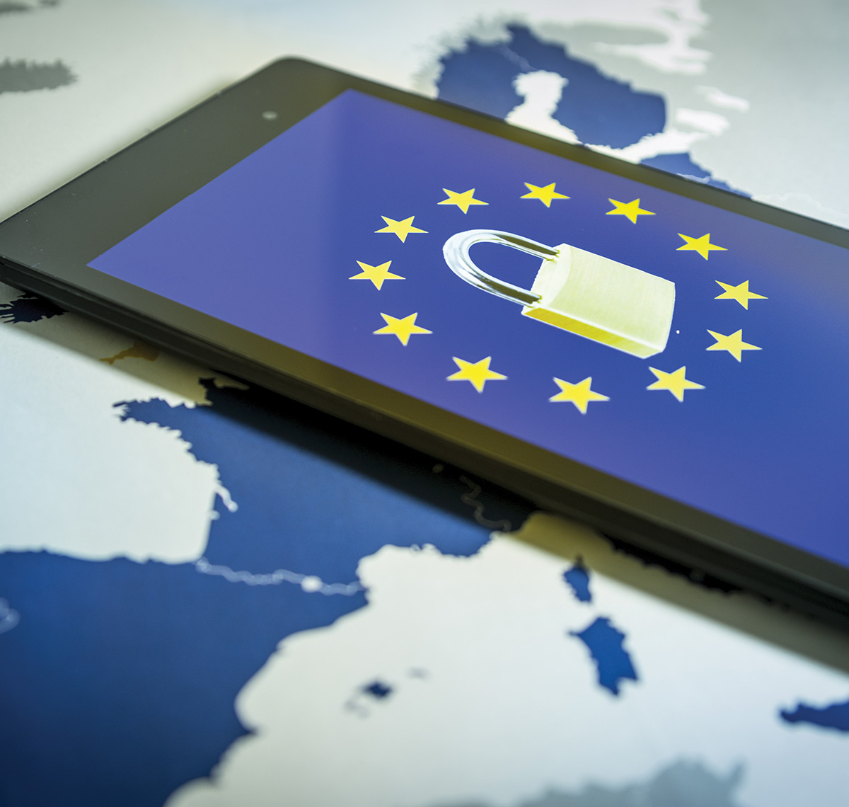
he European Union’s (EU’s) 2024 Cyber Resilience Act makes complying with the cybersecurity standards in the Radio Equipment Directive (RED) mandatory. If your product has Bluetooth, Wi-Fi, or other wireless connectivity in it, and you intend to sell in Europe, it is likely that you will need to comply with Chapter 1, Article 3, Item 3(d), 3(e), and 3(f) of the RED before August 1, 2025. Your firmware developers may need a significant amount of time to implement the provisions, so if you have not already started securing your product to the new regulation, you need to do so now.
Since the new regulation is extremely vague, the European Telecommunications Standards Institute (ETSI) came up with a set of related standards to clarify the requirements that include:
- ETSI EN 303 645 for the manufacturers to follow; and
- ETSI TS 103 701 for test labs to follow.
- Devices capable of communicating over the Internet (either directly themselves or through another device, like a smartphone);
- Toys and childcare equipment; and
- Wearables (smartwatches, etc.).


his is the first of seven articles devoted to the topic of shielding to prevent electromagnetic wave radiation. The shielding theory is based on the accepted theory originally presented in [1] and embraced by many EMC experts [2,3,4]. The results presented here are valid under the assumption of a uniform plane wave with normal (perpendicular) incidence on a boundary between two media.
- reflection and transmission of electromagnetic waves at the boundaries of two media
- radiated fields of the electric and magnetic dipole antennas
- wave impedance of an electromagnetic wave
new version of Technical Report TR18.0-01-25 (TR18) on ESD Electronic Design Automation (EDA) Checks by the ESD Association’s Working Group 18 is about to be released. This article, divided into Part 1 and Part 2, provides guidelines for the EDA industry and the ESD design community for establishing a comprehensive ESD verification flow to address the ESD design challenges of modern ICs. Part 1 covered the concept of ESD checks throughout the IC Design Flow, including Schematic-based and Layout-based ESD checks. Part 2 covers Package-level and System-level checks, ESD Circuit simulation, and ESD TCAD simulation, completing the coverage of all ESD EDA checks described in the Technical Report.
To ensure that the designed protection levels are maintained across all package options, the current state of package-level ESD verification involves several critical steps: extracting metadata of die pads and package pins, setting up EDA tools, defining ESD targets for each signal IO and supply pin, applying appropriate ESD rules on design, and verifying the integrity of the overall ESD protection network considering the additional RLC paths introduced by the package.
At home.
on the go.


You can do that here.
View Index
 Visit In Compliance’s booth at these events!
WPTCE 2025IEEE Wireless Power Technology Conference and Expo
June 15-20
IMS 2025 – IEEE International Microwave Symposium
June 26
Cybersecurity Maturity Model Certification for Federal Government Procurements
July 13-18
2025 IEEE International Symposium on Antennas and Propagation & ITNC-USNC-URSI Radio Science Meeting
July 31
Internet of Things: Testing and Protections for Devices and Systems
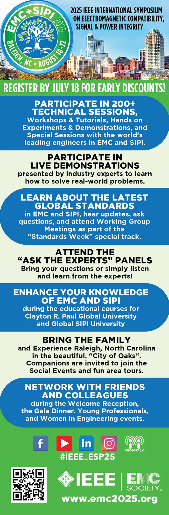
August 18-22
2025 IEEE International Symposium on Electromagnetic Compatibility, Signal & Power Integrity (EMC + SIPI)
Radio Regulations for Module Integrators
September 1-5
EMC Europe
September 13-18
47th Annual Electrical Overstress/Electrostatic Discharge Symposium
September 21-26
European Microwave Week 2025
September 25
2025 Minnesota EMC Event