of a CDM Discharge
Cable Discharge Events
Why Resistance Requirements Differ by Industry and
Why Standards Matter
How and Why Varistor Failure Occurs
Including the Effect of Multipulse Surges

Cable Discharge Events
Why Resistance Requirements Differ by Industry and
Why Standards Matter
How and Why Varistor Failure Occurs
Including the Effect of Multipulse Surges
All you
need in one
small package
All you
need in one
small package
On-Time
Delivery
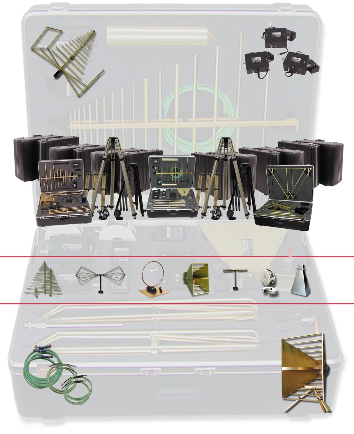
Don’t Leave home without it. A.H. Systems provides many models of Portable Antenna Kits, each containing all the necessary Antennas, Current Probes, and Cables to satisfy numerous customer requirements. Excellent performance, portability (compact size and lightweight), along with ease of setup make all of the Antenna Kits your choice for indoor or field testing. Loss and breakage are virtually eliminated as each component has a specific storage compartment within the case. All Antenna Kits are accompanied with a Tripod and Azimuth & Elevation Head, both contained in a Tripod Carrying Case…and don’t forget your keys!


ISSN 1948-8254 (print)
ISSN 1948-8262 (online)
is published by
Same Page Publishing Inc.
531 King Street, Suite 5
Littleton, MA 01460-1279
tel: (978) 486-4684
fax: (978) 486-4691
©Copyright 2020 Same Page Publishing, Inc. all rights reserved
Contents may not be reproduced in any form without the prior consent of the publisher.
While every attempt is made to provide accurate information, neither the publisher nor the authors accept any liability for errors or omissions.
publisher
bruce@brucearch.com
keith.armstrong@
cherryclough.com
Leo@EisnerSafety.com
dgerke@emiguru.com
ken.javor@emcompliance.com
kenrossesq@gmail.com
wernerschaefer@comcast.net
Subscriptions outside North America are $129 for 12 issues. The digital edition is free.
Please contact our circulation department at circulation@incompliancemag.com

According to a Forfeiture Order issued by the FCC in late July, the company “advertised and sold on its website to U.S. consumers dozens of models of auto/video transmitters for use with unmanned aircraft systems (drones), without regard to whether those AV transmitters were compliant with the…Commission’s rules.”
The devices reportedly provide a video link between transmitters mounted on drones and drone users but can operate outside of frequency bands designated for amateur use, thereby requiring FCC certification.
The FCC’s Spectrum Enforcement Division initially investigated HobbyKing in 2016 after receiving multiple complaints regarding the company’s marketing of the illegal transmitters. Subsequent investigations by the FCC determined that HobbyKing marketed at least 65 different transmitter models that had not been FCC certified.
According to reported posted to the Brinkwire website, inspections of the engine coverings, also known as nacelles, will be required prior to the FAA providing Boeing with clearance to fly the 737 MAX aircraft. While the company successfully argued that the coverings provided a sufficient defense against lighting strikes, the FAA believes that “strong electromagnetic fields could cause a loss of power or faulty readings in the cockpit because of inadequate shielding around wiring.”

his article discusses the basics of a step-down (buck) DC Switched-Mode Power Supply (SMPS). It should serve at an entry-level tutorial and a building step towards the more advanced designs.
The first step in this process consists of creating a Pulse-Width Modulated (PWM) version of the DC input signal, as shown in Figure 2.
The output signal shown in Figure 2 is far from the desired output signal described in our objective. Namely: 1) it is a constant signal only when the transistor is ON, 2) its level, when the transistor is ON, is not lower than the input signal, and 3) it contains high harmonic content during the transition times, [1].
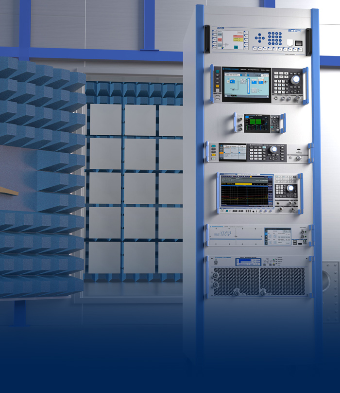
► Virtually explore an EMC lab
► Zoom in to see details with ease
► Learn more about each instrument
► Download brochures and watch videos


n the past, fiber-optic communication was used primarily for long-distance communication (50 km and beyond). Only a limited number of these high-end interface products were required worldwide. More recently, companies running large data centers (Facebook, Google, Amazon) have been replacing the traditional copper cabling between server racks (Figure 1). The copper-based approach is considered a bottleneck for further improvements in data transfer capacity. Optical communication can dramatically increase the bandwidth between servers while reducing complexity, power consumption, and cost.
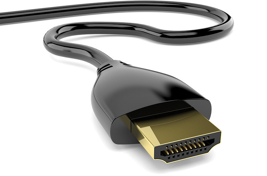
able discharge events (CDE) occur when a cable is plugged into an electrical system and when the cable and the system are at different potentials. CDE can cause system failures such as system lock up, requiring a reboot, and even physical damage.
There have been numerous technical papers on the subject, and ESDA Working Group 14, System Level ESD, has been considering the development of a test standard to screen for this issue for some time. The problem is that there is no single “worst-case” event that is CDE. There are many types and qualities of cable, multiple ways that cables and system can get to different potentials before being connected, and the far end of the cable may or may not be connected to another electrical system or device.
In this article we will review our current understanding of some of the issues with CDE. At the same time, we welcome your help in developing a CDE test method (or methods) to address the issues you have encountered. Please contact us to share your own experiences with CDE, and the real-world problems you believe we need to consider in this process.
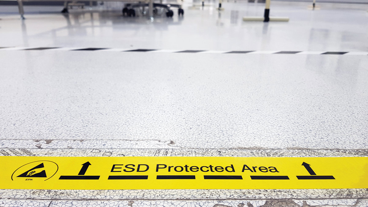
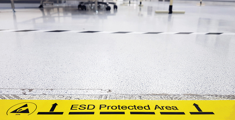
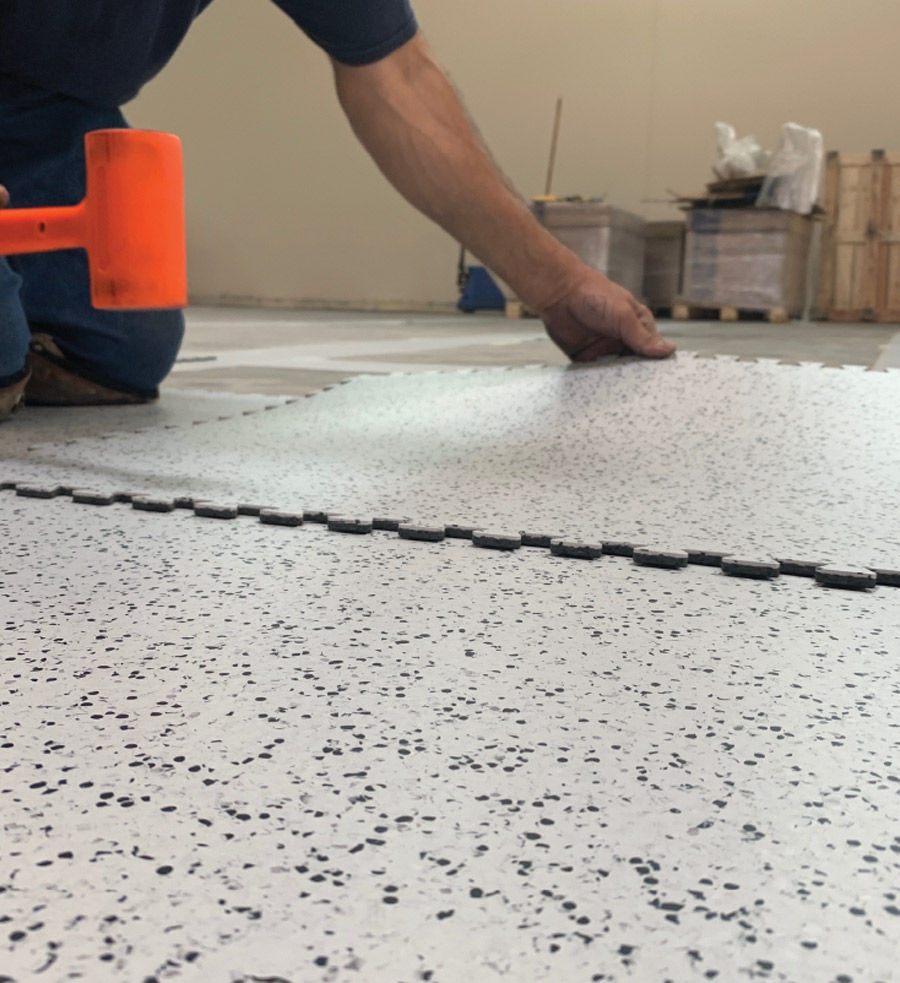
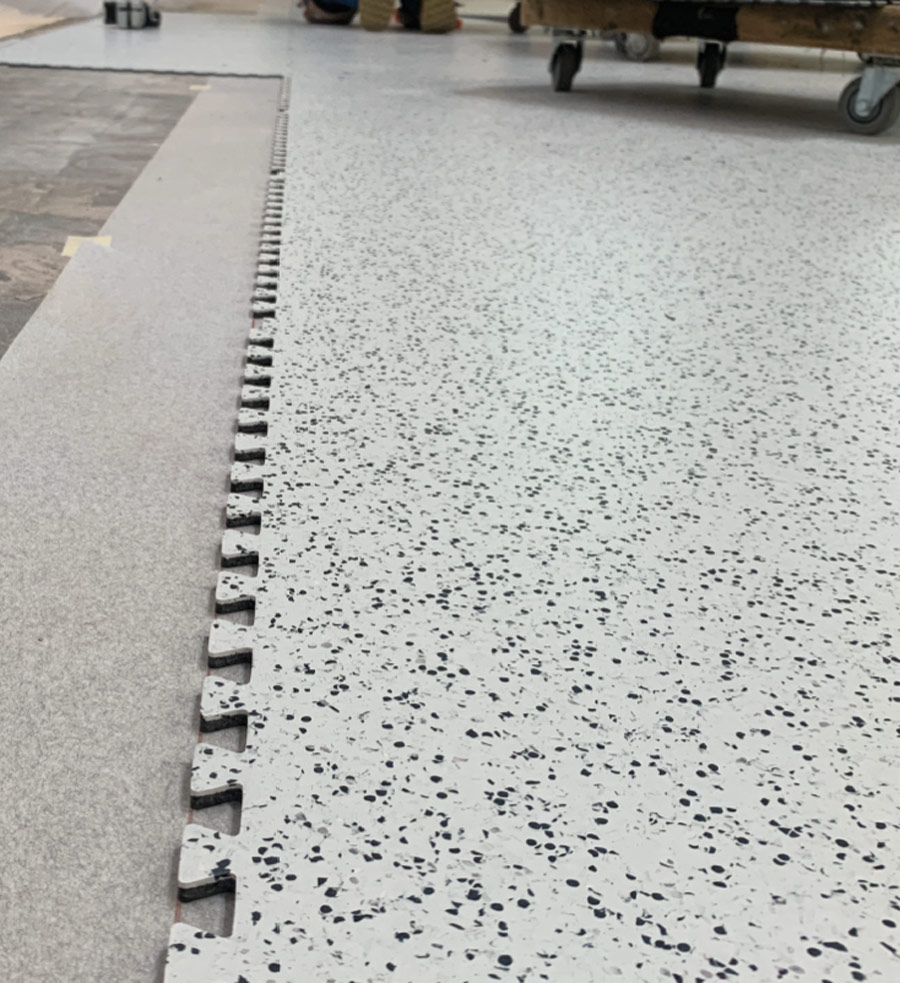
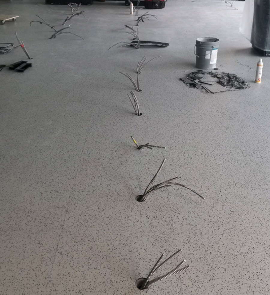
n access floor contractor was bidding a project calling for “static dissipative” flooring. Like many contractors, the project manager viewed the terminology from a generic perspective. Most laymen equate the term static dissipative (SD) with any flooring type that is marketed for the purposes of mitigating the discharge of static electricity. They do not realize there is a distinction between a conductive floor and a dissipative floor and that there may be a practical reason for choosing one over the other.
Since the architectural specs did not include electrical resistance parameters, cite-specific industry standards, or require that resistive properties be tested before final acceptance, the project manager felt comfortable bidding any type of ESD flooring. In this instance, she proposed a conductive floor for an FAA flight tower, when in fact the FAA requires flooring to measure in the static-dissipative range.
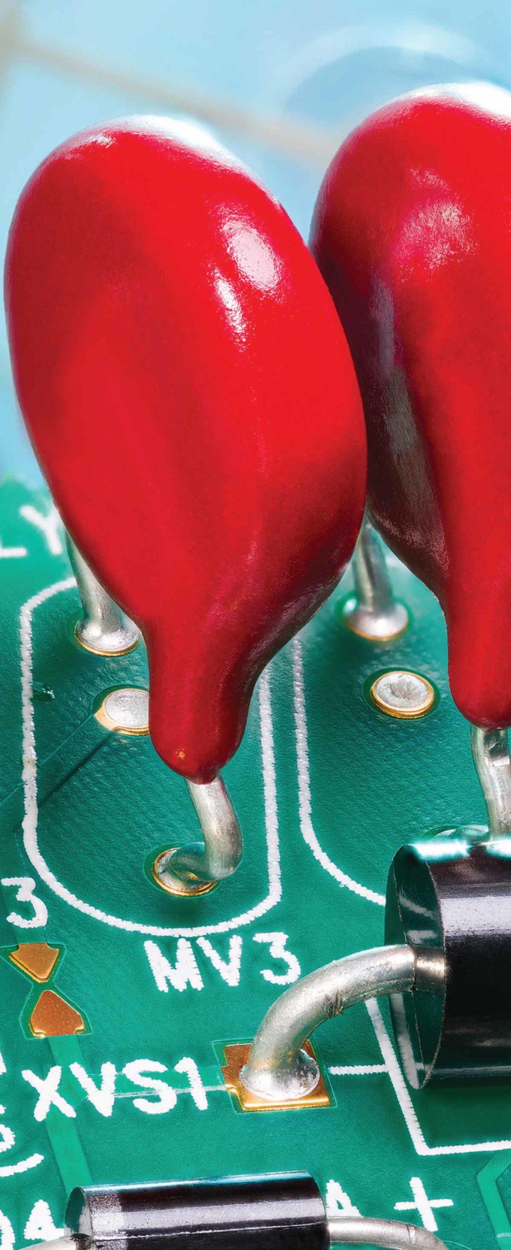
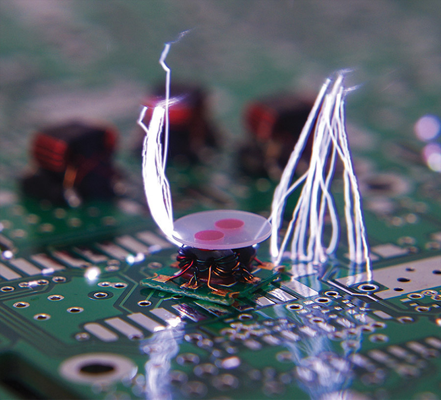
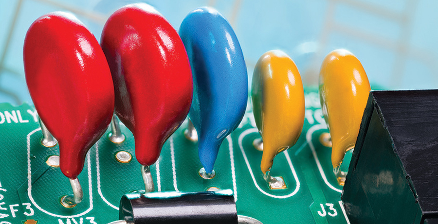
he year was 2011, and an experiment was being done in China to record the effects of a triggered lightning flash on an overhead transmission line. The line was instrumented to record the induced currents, and the instruments were protected with a metal oxide varistor (MOV).1 The lightning flash recorded consisted of multiple return strokes, none of which exceeded the Imax rating of the MOV. But, much to the surprise of the experimenters, the MOV was damaged.
How could this happen? And more importantly, why might Imax not be a good basis for selecting an MOV for lightning protection, and are there alternatives? To help answer these questions, we’ll discuss in this article what an MOV is and how the way it is made influences its behavior when surged, how failures occur, and how multipulse surges differ from single surges in their effect on MOV properties.
In order to understand failure, it’s useful to discuss how varistors are made. In this regard, there are three things of note.
First, varistors are a ceramic material composed primarily of zinc oxide (ZnO). At ambient conditions, ZnO crystallizes into a hexagonal wurtzite structure, as shown in Figure 1, where the large balls represent Zn and the small balls represent oxygen (O). This is a complicated structure that, if it crystallized perfectly, would be an insulator. But because the crystallization process isn’t perfect, the resulting oxygen vacancies or zinc interstitials cause this structure to become a wide-gap semiconductor having a relatively low resistivity of 1 – 100 Ω-cm at room temperature.
Second, a varistor is not one uniform wurtzite crystal, but many which coalesce into grains. To make ZnO into a varistor, a small amount of Bi2O3 is added. The Bi2O3 goes into the grain boundaries, as shown in Figure 2. In addition to Bi2O3, MnO may be added to enhance the nonlinear properties; Sb2O3 to control the ZnO grain growth; and a small amount of Al2O3 to increase the ZnO grain conductivity.
The Bi2O3 between two ZnO grains results in the formation of back-back Schottky diodes. So essentially, a varistor is a series-parallel arrangement of n-type material separated by back-back Schottky diodes having a voltage drop of about 2V-3V per grain boundary Junction (independent of grain size). According to He [1], this structure can be characterized electrically by Equation (1).
View Index
EOS/ESD Symposium
September 23-25
EMC Europe Virtual Event
September 28 – October 1
Applying Practical EMI Design & Troubleshooting Techniques (Tewksbury, MA)
October 5-8
MIL-STD-810G: Understanding, Planning and Performing Climatic and Dynamic Testing
October 6-8
ETS-University: Automotive Course
October 12-14
ESD Auditor Certification Course
Ground Resistance Training Seminar
October 20-21
ETS-University: TILE! Software
October 20-22
Applying Practical EMI Design & Troubleshooting Techniques (Milpitas, CA)
October 27-29
Applying Practical EMI Design & Troubleshooting Techniques (Bannewitz, Germany)


The EOS/ESD Symposium represents the world’s leading forum on electrostatic discharge and electrical overstress. This year, we are thrilled to invite you to experience our brand new hybrid event. With our hybrid event, you can attend the Symposium face-to-face and we are following the most advanced safety precautions available. You may also experience the Symposium in real-time via livestream or enjoy On-Demand access after the live event concludes from the comfort of your home or office. The choice is yours!
Since 1979, industry professionals from all over the world have flocked to the EOS/ESD Symposium to enjoy the unique opportunity to meet professionals with hands-on experience in their fields as well as learn from and exchange knowledge with the greatest industry experts of our time. This is an exciting time, and we are committed to bringing you a one-of-a-kind hybrid event that sets the bar high, pioneering a new vision for our events, and setting a path for others to follow.
We are proud to offer you 3 tracks over 5 days of tutorials and technical presentations. These will feature different delivery mechanisms and will involve ways for you to engage presenters virtually if they or you are present at the face-to-face event! Instructors and presenters will be live at the event, some will be presenting from their home base via livestream broadcasting to the event site, and some will provide a pre-recorded presentation and join us for Q&A sessions. We also welcome you to enjoy industry exhibits from exhibitors showcasing a wide variety of ESD solutions from established products to leading-edge innovations, on-site and also through virtual exhibits.
On top of these incredible offerings, we are also pleased to present this year’s Keynote “The Role of Photons in Hardware Security” by Dr. Shahin Tajik of the Florida Institute for Cybersecurity (FICS) Research at the University of Florida who is joining us via livestream.


