Common Mode Filter Design Guide
Health Monitoring and Prediction of Cells in a Battery Module or Pack Under Operating Condition

Common Mode Filter Design Guide
Health Monitoring and Prediction of Cells in a Battery Module or Pack Under Operating Condition


ISSN 1948-8254 (print)
ISSN 1948-8262 (online)
is published by
Same Page Publishing Inc.
451 King Street, #458
Littleton, MA 01460
tel: (978) 486-4684
fax: (978) 486-4691
©Copyright 2022 Same Page Publishing, Inc. all rights reserved
Contents may not be reproduced in any form without the prior consent of the publisher.
While every attempt is made to provide accurate information, neither the publisher nor the authors accept any liability for errors or omissions.
publisher
bruce@brucearch.com
keith.armstrong@
cherryclough.com
Leo@EisnerSafety.com
dgerke@emiguru.com
ken.javor@emcompliance.com
kenrossesq@gmail.com
wernerschaefer@comcast.net
Subscriptions outside North America are $129 for 12 issues. The digital edition is free.
Please contact our circulation department at circulation@incompliancemag.com


Amateur Radio Operator Fined for Interfering with Fire Suppression Communications


The Untold Electromagnetic Backstory

n February 1, 2003, NASA’s Space Shuttle Orbiter Columbia broke apart upon re-entry into the earth’s atmosphere, tragically ending the lives of seven highly-trained and experienced astronauts. This accident not only personally affected the extended families of the astronauts, it permanently changed the trajectory of the U.S. manned space program. After a lengthy accident investigation and root cause analysis, the Shuttle successfully flew again on July 26, 2005. The Shuttle’s subsequent 22 missions made possible the completion of the assembly of the International Space Station (ISS) and provided a final service call for the Hubble Space Telescope, before the Shuttle fleet was retired in 2011.


he Internet of Things (IoT) is quickly being adopted for use in mission-critical applications for several reasons. First, the IoT now incorporates increasingly sophisticated technologies, such as artificial intelligence (AI), augmented reality, edge computing, sensor fusion, and mesh networking to tackle problems of increasing difficulty and importance. Second, as recent supply chain challenges have demonstrated, margins for error and delay are slim at best. Third, the demand for increased healthcare, combined with resource scarcity, means many medical services must decrease in cost and become more efficient. Finally, the desire to conserve resources means devices must last longer and perform more reliably.
These trends present numerous business opportunities in fields that serve human health, safety, food production, environmental protection, and other key aspects of human flourishing. As technical challenges grow, each of the 5 Cs + 1 C of the IoT becomes more important. Some of these can use artificial intelligence (AI) as part of the solution.


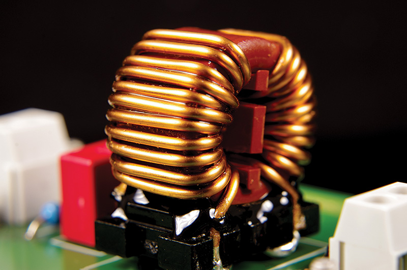
he selection of component values for common mode filters need not be a difficult and confusing process. The use of standard filter alignments can be utilized to achieve a relatively simple and straightforward design process, though such alignments may readily be modified to utilize pre-defined component values.
Line filters prevent excessive noise from being conducted between electronic equipment and the AC line. Generally, the emphasis is on protecting the AC line. Figure 1 shows the use of a common mode filter between the AC line (via impedance matching circuitry) and a (noisy) power converter. The direction of common mode noise (noise on both lines occurring simultaneously referred to as earth ground) is from the load and into the filter, where the noise common to both lines becomes sufficiently attenuated. The resulting common mode output of the filter onto the AC line (via impedance matching circuitry) is then negligible.


Tin whiskers are small, typically hair-like structures that can form naturally from the surface of tin components in electronic devices (Figure 1). Tin whisker formation is a well-documented phenomenon that has been studied for decades. Throughout this time, little consensus has been reached regarding the particular mechanisms behind tin whisker formation. Whisker formation is believed to be a diffusion-controlled process motivated by stresses, both internal and external; however, the wide range of factors that may produce material stresses makes it exceedingly difficult to identify or isolate individual factors.


Part 1: Fundamental Concepts
his is the first of two articles devoted to an eye diagram. In this article, the fundamental definitions and concepts are presented. The next article will show the impact of driver, receiver, and interconnect properties on signal quality using data eye and data eye mask concepts while evaluating several different HDMI cables.
An eye diagram is basically an infinite persisted overlay of all bits captured by an oscilloscope to show when bits are valid. This provides a composite picture of the overall quality of a system’s physical layer characteristics. This picture covers all possible combinations of variations affecting the signal: amplitude, timing uncertainties, and infrequent signal anomalies.

Misconceptions Regarding Current Flow to the IC
here is often confusion about the interaction between IC-level component ESD protection and the appropriately required system-level ESD protection strategy. System-level ESD requirements (like IEC 61000-4-2 [1] and ISO 10605 [2]) are intended for electronic systems, not for individual integrated circuits (ICs). However, it is becoming increasingly common to see supplier claims and customer expectations of system-level ESD performance at the IC-level. While such performance may be desirous to both suppliers and customers, there is significant ambiguity about what such claims and expectations mean. Generally, little information is available about the actual system surrounding the IC. How does the customer interpret an IC-level performance claim without a specific system, and how does a supplier design for and guarantee performance? Certainly, the IC has been tested in some systems to facilitate the datasheet specification, but how did the designer define that system, and how does it compare to the final customer system? This lack of specificity implies that a general capability of the IC applies to a wide range of unique system requirements when, in fact, there are significant challenges to integrating an IC into a single unique system. These challenges extend beyond safely conducting the current during the ESD event—systems are often powered, and the failure criteria can include functional operation during and after the ESD event. But gaps exist that must be considered even if the problem is reduced to a simple guarantee that current can be safely conducted during the ESD event.

esign engineers who have been to an EMC testing laboratory must be familiar with the large selection of ferrite cores that a test lab often provides. For a product with a mains lead or a system consisting of long cables (HDMI, USB, etc.), the most common EMC failures often include conducted emissions in the frequency range of 9 kHz and 30 MHz and radiated emissions in the 30-300 MHz range. In such cases, cables often become effective antennas, and ferrite cores are generally used to locate and suppress the noise (at least during the troubleshooting stage).
The practice of using ferrite cores on cables is often performed using a trial-and-error approach. Engineers place a ferrite core on one end of a cable and measure the performance. If the noise at the frequency range of interest is reduced with the placement of the ferrite core, this means the approach works. If not, the ferrite core is then removed and placed in another cable.
In this column, I offer a brief summary of a more systematic approach for using ferrite cores on cables. Hopefully, this summary can serve as a “ferrite core checklist” for design and test engineers.


View Index
IEEE EMC+SIPI 2022
September 5-8
EMC Europe 2022
September 13-15
The Battery Show
September 13-15
Fundamentals of Random Vibration and Shock Testing Training
September 13-16
Lab Techniques, Robust Design, and Troubleshooting
44th Annual EOS/ESD Symposium
September 20-22
ISPCE 2022
September 29
2022 Minnesota EMC Event
October 6-7
Fundamental Principles of Electromagnetic Compatibility and Signal Integrity
October 9-14
AMTA 2022
Military Standard 810 (MIL-STD 810) Training
October 18
2022 San Diego Test Equipment Symposium

is your
Key to Success
80-6000MHz, 750W/200W
Our Creativity has no Competition
80-6000MHz, 750W/200W
Our Creativity has no Competition
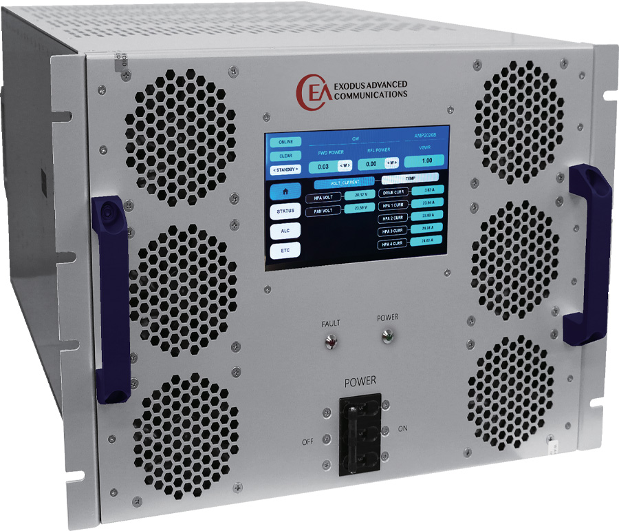
… we are redefining
Ingenuity!

Las Vegas, Nevada 89120
Tel: 702-534-6564
Web: www.exoduscomm.com • Email: sales@exoduscomm.com
