Laboratory Automation with PyVISA
Laboratory Automation with PyVISA


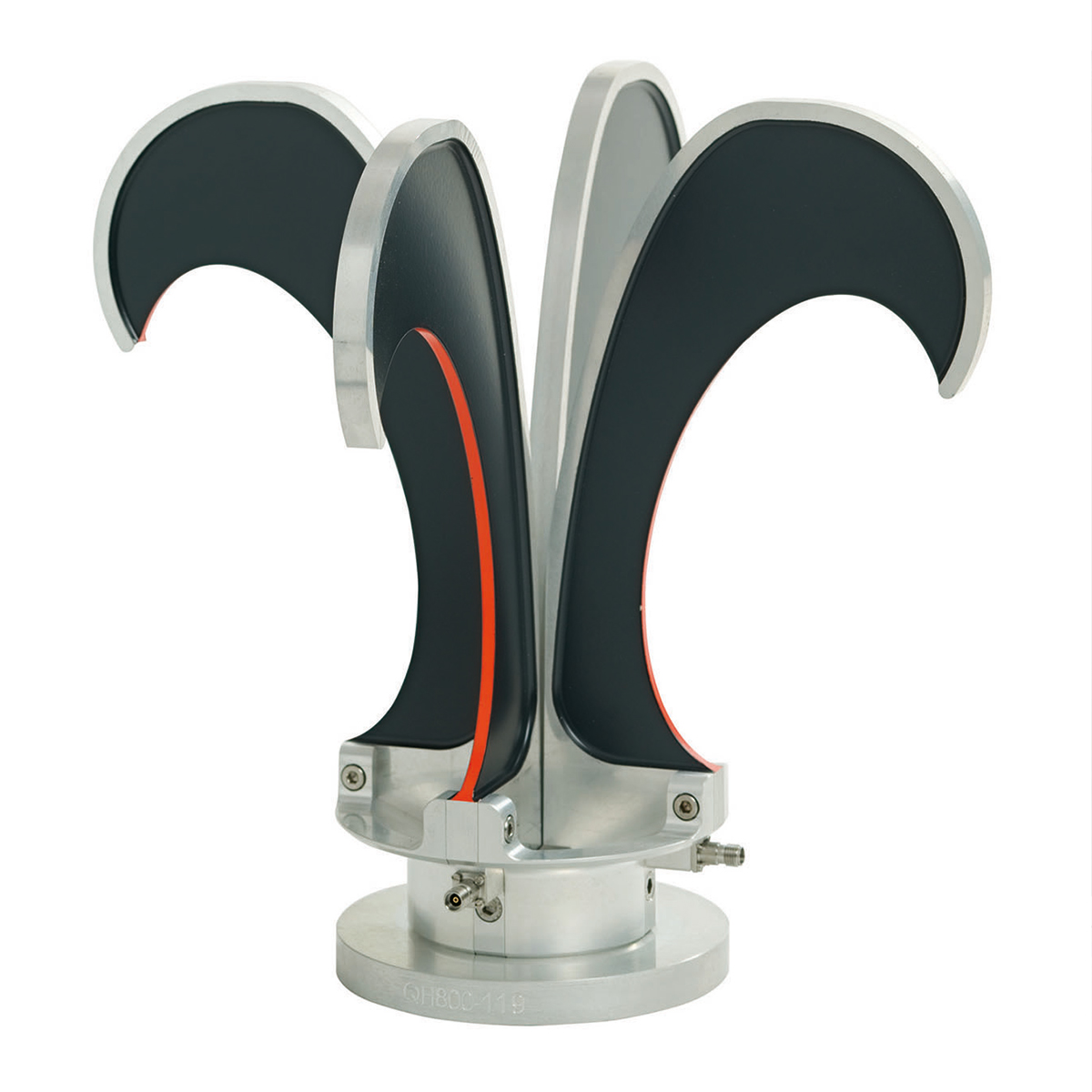
solid-state amplifiers
Visit us at www.arworld.us
Contact us at ari-sales@ametek.com or telephone 215.723.8181


ISSN 1948-8254 (print)
ISSN 1948-8262 (online)
is published by
Same Page Publishing Inc.
451 King Street, #458
Littleton, MA 01460
tel: (978) 486-4684
fax: (978) 486-4691
© Copyright 2024 Same Page Publishing, Inc. all rights reserved
Contents may not be reproduced in any form without the prior consent of the publisher. While every attempt is made to provide accurate information, neither the publisher nor the authors accept any liability for errors or omissions.
editor-in-chief
Please contact our circulation department at circulation@incompliancemag.com
According to an FCC press release announcing the rule change, the new rules are the result of years of extended discussions and collaboration by members of the FCC’s Hearing Aid Compatibility Task Force. Once implemented, the 100 percent HAC requirement will provide an additional 48 million Americans dealing with hearing loss with the flexibility…
The case is perhaps most interestingly illustrated by a decision by the U.S. Food and Drug Administration (FDA) regarding its review of an electric toothbrush that uses radiofrequency…

Fundamentals of Random Vibration and Shock Testing Training
January 28-30, 2025
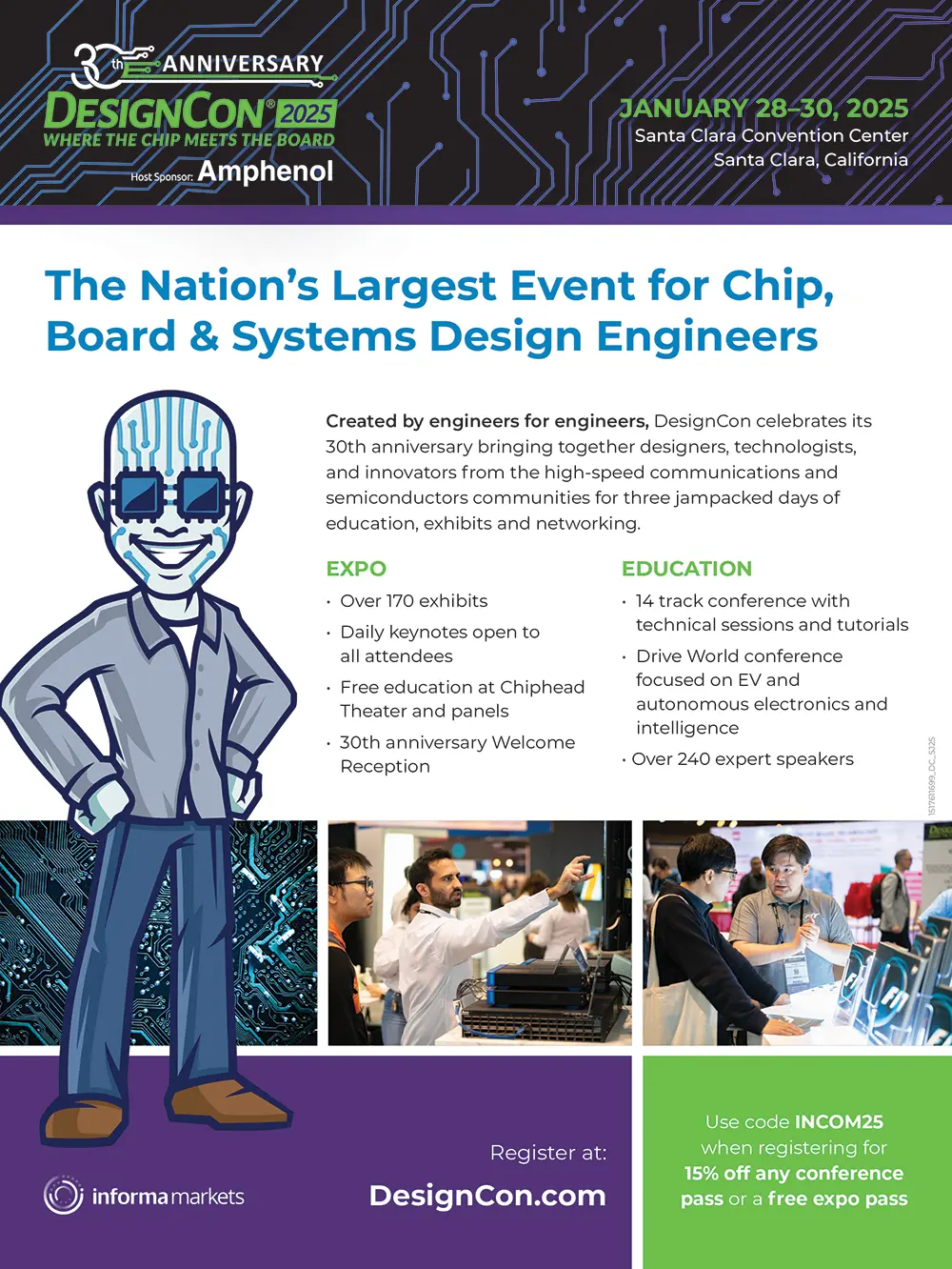
DesignCon 2025

et’s use the basic tools and spectrum analyzer setup I described in the last two months and use them to characterize an actual embedded processor board based on the Arduino design. I’ll be using an “OSEPP Bluetooth” board, but you can use anything on hand or similar (Figure 1). The schematic and board layout are available in Reference 1. While most Arduino-based boards use linear regulators, I chose this board from my collection because it includes a DC-DC converter and uses a two-layer design with obvious EMC issues.
Let’s make some near field probe measurements; first on the DC-DC converter. This is easy to identify because of the large 22µH inductor at the bottom of the board. We’ll non-invasively couple to the inductor (Reference 2), which is connected to the MAX1676 boost converter. Figure 3 shows the resulting frequency domain plot. Placing the spectrum analyzer in Max Hold mode, we can see a lot of switching energy extending out to 200 MHz. You’ll notice that for each plot, I record the system noise floor (yellow trace). I also placed markers at some of the resonant peaks, which we may use in possible future analyses.
Part 2
n the last blog, we discussed how the FAA and aircraft industry recognized that personal electronic devices, or PEDs, were causing problems aboard aircraft. With the proliferation of PEDs onboard, and especially those with wireless capabilities, action was needed quickly to address safety concerns. The FAA requested the RTCA form a new committee, SC-202, made up of over 100 individuals from the aircraft industry, airlines, computer, medical, telecommunication, and commercial electronics industries, consultants, FAA, and elected officials. The group was formed specifically to address PEDs that had transmitters, cellular technology, wireless radio frequency networks, and the like. These transmitting PEDs are referred to as T-PEDs.
There was a recognition that guidance for the use of T-PEDs was extremely important. Incidents were being reported, often anecdotal and erroneous or misinterpreted. However, it created much interest in the media and the public. Several issues with PEDs were found, including:
lectricity meters and other similar devices have their own set of unique standards and requirements. The following describes these requirements, the challenges involved, and the status of some requirements.
For meters going to Mexico, Comisión Federal de Electricidad (CFE) standard G0000-48-2010 is required for stand-alone meters. G0000-48-2010 derives its requirements from the IEC meter standards. In 2025, an entirely new standard for meters sold into Mexico will take effect. This standard is NOM-001-CRE and brings with it an entirely new set of requirements for meters and requires meters to have the capability for easy replacement via some type of extractable case.

ot long ago, the electrification of consumer machinery was primarily limited to hybrid electric vehicles (HEVs), marketed as the next generation of clean propulsion but largely out of reach for the average consumer. Now, with the advent of affordable, high-end microcontroller units (MCUs) and high-efficiency semiconductors, the adaptation of motor control has become more accessible, expanding electrification into secondary markets such as turf care and agricultural equipment, in addition to a growing HEV market. This shift means that embedded system or module development engineers are encountering new challenges associated with electric drives.
Central to these advanced systems are the power electronic components that constitute the inverter system. These components are responsible for converting DC voltage from a generator or battery into an appropriate signal to drive a three-phase motor. Designing and interfacing with the control electronics of inverters present unique challenges, particularly in managing signal integrity and mitigating noise. To illustrate these complexities, a typical inverter system is depicted in Figure 1.


urrent probes are used to perform conducted emission (CE) measurements in accordance with various product standards like CISPR 11, CISPR 25, or CISPR 32. All these product standards refer to the basic standard CISPR 16-1-2 (2014), which includes normative specifications for current probes in clause 5.1.3. Some of the current specifications include:
- Insertion impedance: 1 Ω impedance maximum;
- Transfer impedance: 0.1 Ω to 5 Ω in the flat linear range; 0.001 Ω to 0.1 Ω below the flat linear range (current probe terminated into 50 Ω load);
- Added shunt capacitance: less than 25 pF between the current probe housing and measured conductor; and
- Frequency response: Transfer impedance is measured over a specified frequency range to calibrate the probe; the range of individual probes is typically 10 kHz to 100 MHz, 100 MHz to 300 MHz, and 200 MHz to 1,000 MHz.
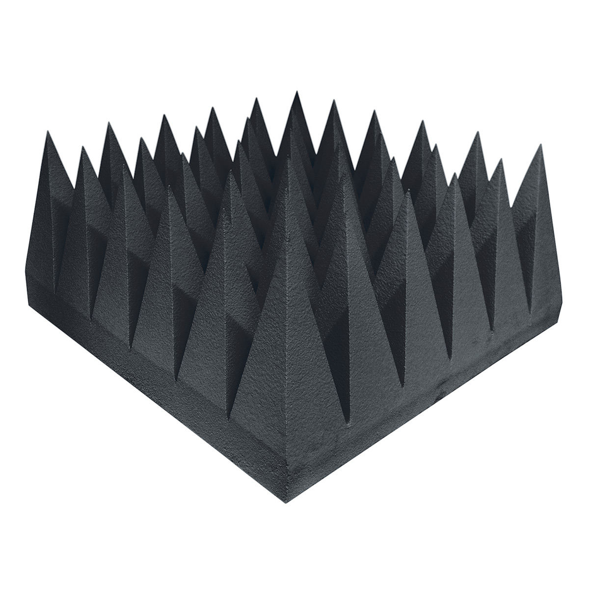
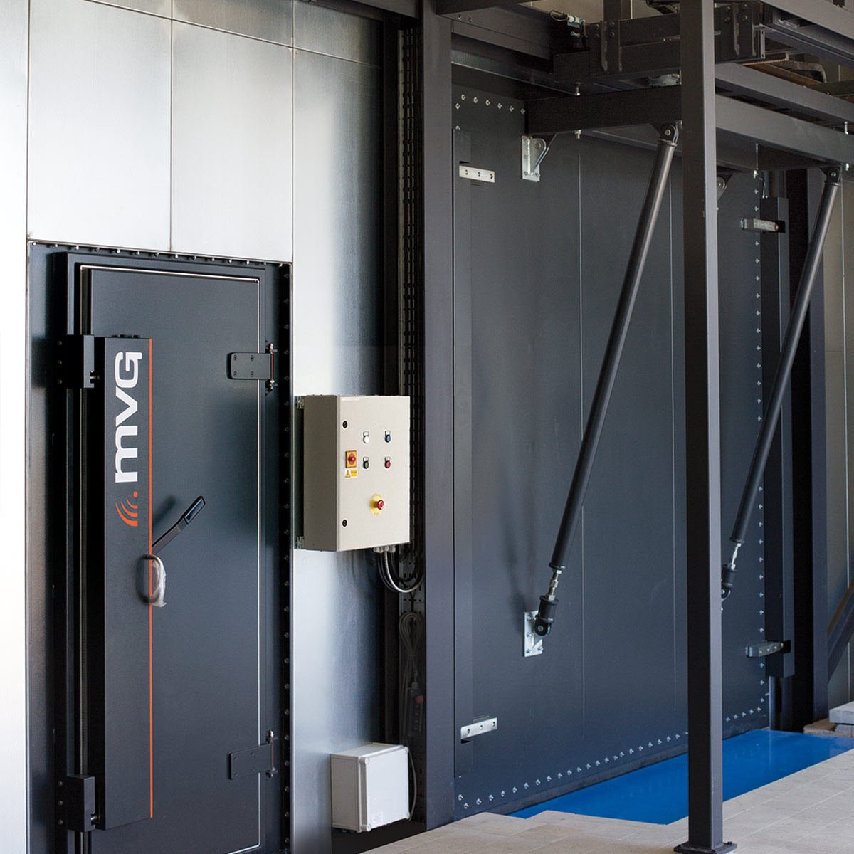
- EMC Test Chambers
- Shielded Doors
- RF Shielded Rooms
- EMC Antennas
- EMC Accessories


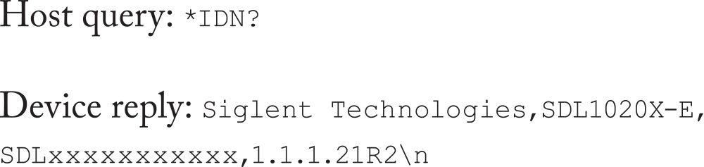
ython has become a widely used programming language in the area of electronic test automation, especially when used with the PyVISA library. While the fundamental principles of lab automation have been around for a long time (i.e., the SCPI protocol), Python and PyVISA have made it easy to get started quickly with test automation. Once data has been collected, Python also has a plethora of data analysis tools (pandas, scipy, scikit, etc.) that are useful in analyzing data.
In this article, I will introduce how to interface with instruments using Python/PyVISA and give a practical example of measuring power supply efficiency. Finally, I will introduce how to plot gathered efficiency data directly in Python.
HANDBOOK

ost markets of electrical/electronic devices require some form of third-party safety agency certification of the products before they can be sold into that market. In North America, this involves working with a third-party safety certification agency, also known as a Nationally Recognized Testing Laboratory (NRTL), the entity that verifies the product complies with the applicable UL/CSA safety standards.
Working with an NRTL such as UL or CSA can be very challenging and frustrating. The usual experience is that projects are late, costs are overrun, and certification reports are often inaccurate. This is not always the fault of the NRTL.

Element Materials Technology operates advanced battery testing labs offering comprehensive services for batteries used across industries like automotive, aerospace, consumer electronics, medical devices, and energy storage. These labs ensure batteries meet stringent safety, reliability, and performance standards, especially for lithium-ion, lithium-metal, and solid-state technologies.


With facilities worldwide, Element provides testing close to manufacturing and distribution hubs, enhancing efficiency and speed to market. By tailoring testing programs and guiding clients through certification, Element helps companies deliver safe, reliable, and high-performance battery solutions for global markets.
Contact:
contact.us@element.com
(888) 786-7555
https://www.element.com/connected-technologies/battery-testing-services

In addition, we have the capability in our lab to perform a wide range of EMC, Electrical and ESD testing for all the major industries including, but not limited to Automotive, Aerospace, Defense, Medical, Industrial, Commercial, Consumer, Agricultural and others. Our in-house test capability not only allows us to pre-screen electronics to identify issues, but we also perform diagnostics to find sources efficiently and identify solutions quickly. We support our customers at any stage of product development (including with production or field issues) so they can pass compliance testing with confidence and get into the marketplace on time. Contact us today to learn how we can help you prevent or resolve an EMC or High-Speed SIPI challenge while saving you time and money. Call us at: +1 833 EMC-SIPI (+1 833 362-7474) or email us at: sales@e3compliance.com.
sales@e3compliance.com | https://www.e3compliance.com
Scott Mee
+1 833-362-7474 (833-EMC-SIPI)
sales@e3compliance.com
https://www.e3compliance.com

(833) 362-7474
- Automotive & Intelligent Transportation
- Aerospace & Defense
- Medical devices and healthcare
- EMC Pre-compliance Testing
- EMC Diagnostic Testing
- Design Consulting & Remediation
- iNARTE Certified Master EMC Designers
- iNARTE Certified EMC Engineers
Unique Capabilities:
- Design consulting, pre‑compliance and diagnostic testing all under one roof
- Specialized industry leading diagnostic tools for speed an accuracy of diagnosis
- Over 100 years of combined EMC & High‑Speed experience
(888) 786-7555
- Atlanta-Gainesville, GA
- Brooklyn Park, MN
- Dallas Plano, TX
- Irvine, CA
- Washington, Columbia, Oakland Mills
- Medical Devices
- Test and Measurement Equipment
- Battery
- Product Safety
- EMC Testing
- International Compliance
- NRTL
- ISO/IEC 17025 (A2LA)
- CB Testing Laboratory (CBTL)
Unique Capabilities:
- Largest commercial cell and battery cycling capacity
- Large Drive in EMC Chambers
- Full service environmental testing services in addition to EMC, NRTL, and CBTL


his is the third and final article discussing four different circuit models of transmission lines in sinusoidal steady state. In [1], Model 1 and Model 2 were presented. Model 1 was used to present the solution of the transmission line equations. Model 2 introduced the standing waves. Model 3 discussed in [2] led to the evaluation of the values of the minima and maxima of standing waves. This article uses Model 4 to determine the locations of the minima and maxima of standing waves. This determination is first done analytically, followed by the graphical method using the Smith chart.
In Model 3, we are moving away from the source, located at z = -L to the load located at z = 0. Model 4 is shown in Figure 2.
rtificial intelligence (AI) has emerged as a significant game-changer across various industries. This influence of AI has fueled a dramatic increase in silicon fabrication, leading to substantial advancements in the semiconductor industry.
One of the most notable advancements in silicon fabrication and manufacturing is the development of high bandwidth memory (HBM) stacks. This should not be confused with the human body model for electrostatic discharge (ESD) model. These memory die stacks, which are located near the processor, have been increasing in number. This proximity and increased die stacking enhance memory density and the speed and efficiency of data transfer, significantly improving the performance of electronic devices that utilize AI hardware algorithms.
One concern with multiple die stacking is the risk of ESD at the die-to-die (D2D) interface during the manufacturing process. Because of this, there is a requirement to balance the amount of ESD protection on the interface without interfering with the speed, silicon area, and design at the interface. Progressively, advances in the D2D interconnect are becoming smaller and denser, further limiting the amount of acceptable ESD protection.


Subscribe to In Compliance Magazine
Each monthly issue focuses on regulatory compliance issues and expands into in-depth technical coverage of electronic design, testing, and troubleshooting.

You can do that here.
View Index
