Is Wireless Measurement of Human Body Voltage Possible?
(Re)Discovering the Lost Science of Near-Field Measurements, Part 4
Is Wireless Measurement of Human Body Voltage Possible?
(Re)Discovering the Lost Science of Near-Field Measurements, Part 4


Ever Thought Possible
Or contact us at info@arworld.us & 215.723.8181
ISSN 1948-8254 (print)
ISSN 1948-8262 (online)
is published by
Same Page Publishing Inc.
451 King Street, #458
Littleton, MA 01460
tel: (978) 486-4684
fax: (978) 486-4691
©Copyright 2023 Same Page Publishing, Inc. all rights reserved
Contents may not be reproduced in any form without the prior consent of the publisher.
While every attempt is made to provide accurate information, neither the publisher nor the authors accept any liability for errors or omissions.
editor-in-chief
bruce@brucearch.com
keith.armstrong@
cherryclough.com
Leo@EisnerSafety.com
dgerke@emiguru.com
ken.javor@emcompliance.com
kenrossesq@gmail.com
wernerschaefer@comcast.net


Discovering the Lost Science of Near-Field Measurements, Part 4")


The FCC decision was issued in response to petitions from 17 separate state, local, and municipal transportation authorities across the country and two equipment manufacturers. Each individual petitioner sought a waiver of certain Part 90 and Part 95 rules that regulate the operation of dedicated short-range communication (DSRC) based roadside units and onboard units in the upper 30 megahertz of the 5.9 GHz band.
According to a press release published on its website, the National Association for Amateur Radio (ARRL) has filed comments against a proposal that would allow the introduction of high-power digital communications in spectrum directly adjacent to amateur HF bands. The proposal for the change was filed as a petition to the U.S. Federal Communications Commission (FCC) by the…

Feature Article
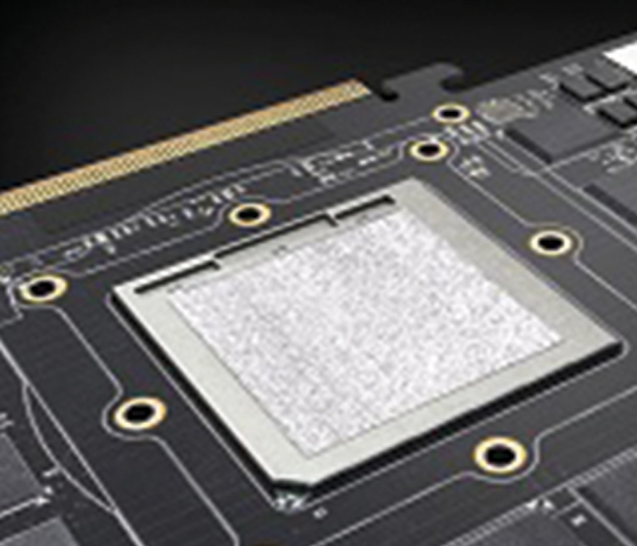
s a technical consultant, I have seen various new technologies implemented in both new and old applications. In the semiconductor industry, WBG devices such as SiC and GaN transistors have been gaining attention due to their small size, fast speed, and better thermal performance. The introduction of these new semiconductors into the consumer market came after a series of military and other commercial applications of the technology in everything from electric vehicles to radar systems.
GaN devices have enabled a much better form factor for product design than their silicon counterparts. As they become cheaper and more available, it is expected that we will see them widely adopted in power-switching modules worldwide.
Technically speaking, GaN semiconductors are high-electron-mobility transistors (HEMTs), meaning they do not have the doped region in a PN junction like MOSFETs. This enables faster electron flow, hence higher switching speed. Because HEMTs do not have the PN structure, they also do not have a body diode. This can have a great impact in applications such as motor drives, where we can now switch on the HEMT for freewheeling rather than relying on the body diode.


igh-speed interfaces are essential to satisfy the need for processing massive amounts of data. In all market segments, from consumer and computing to industrial and automotive, the trend is to introduce innovative technologies or to increase the data rate of existing interfaces to reach gigabit speeds. The computing segment usually leads the race for higher data rates. Just recently, the USB standard was extended to support 80Gbps with its latest revision USB 4.2. In automotive ethernet applications, the data rate will increase up to 25Gbps over a single differential pair.
The extremely high functional density of physical layer (PHY) circuits for all these high-speed interfaces usually does not allow robust on-chip protection against electrostatic discharge (ESD). That is why external ESD protection devices are used to fulfill the system’s ESD requirements. Besides the ESD requirements, all high-speed interfaces need to fulfill the requirements on signal integrity (SI). The ESD device itself introduces a discontinuity into the interface and might violate the limits of SI.


ur ability to measure the charge accumulated by a human being is a critical part of managing electrostatic discharge (ESD) in industrial environments. Unfortunately, these measurements require that the person involved is connected by wire to a high-impedance or electrostatic voltmeter. This is fine in the laboratory but severely limits our possibilities on the factory floor. In this article, we describe how wireless measurements of human body voltage can be made, and why they are important for ESD managers.


his is the final installment of this serialized article. The first installment explained what near and far field measurements entail, and that one-meter measurements are very much near field. The second installment explained the evolution of the earlier 12” and present-day one-meter separation measurements, considerations in antenna selection, the difference between antenna-induced and field strength limits, and the evolution from one to the other. The third installment investigated practical problems arising from the misapplication of field intensity and far-field concepts to near-field phenomena.
This fourth and final installment lists theoretical misunderstandings arising from the erroneous substitution of field intensity for antenna-induced concepts and shows the serious practical outcomes that result from these theoretical mistakes.


Resource
Guide


In Compliance Magazine’s 2024 Product Resource Guide highlights twelve product categories—and offers guidance on choosing and using the right products and services for your applications.
We aim to provide you with the impartial, practical guidance you need to confidently make your compliance products and services purchase decisions in the year ahead.
We hope you’ll find the information compiled in the 2024 Product Resource Guide to be useful, reliable, real-world information you can use immediately.
As always, we’re here to help.

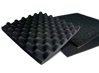
he two primary shielding mechanisms are reflection and absorption. The two combined result in the familiar expression SE(dB) = R(dB) + A(dB), where SE(dB) is shielding effectiveness in decibels, R represents Reflection Loss, and A represents Absorption Loss (both also expressed in decibels). Often, absorption loss (also called penetration loss) is the energy that is not first reflected by the shield that is absorbed by it – the topic of this article.
Note: A third term involved in the SE equation called the multiple reflection factor B is often ignored if A is greater than 9 dB or if the field is electric or plane wave.
his article describes a loss-less impedance matching technique that does not require the use of discrete components but instead uses cables or printed circuit board (PCB) traces, i.e., distributed elements or transmission lines. It is a matching circuit built using a piece of transmission line whose length is equal to a quarter of the signal’s wavelength, hence the name “quarter-wavelength impedance matching transformer” or “quarter-wavelength impedance matching network.” But before jumping into specifics of the quarter-wavelength impedance transformers/networks, let us first discuss the use of discrete components (inductors, capacitors, etc.) and their limitations in matching networks.
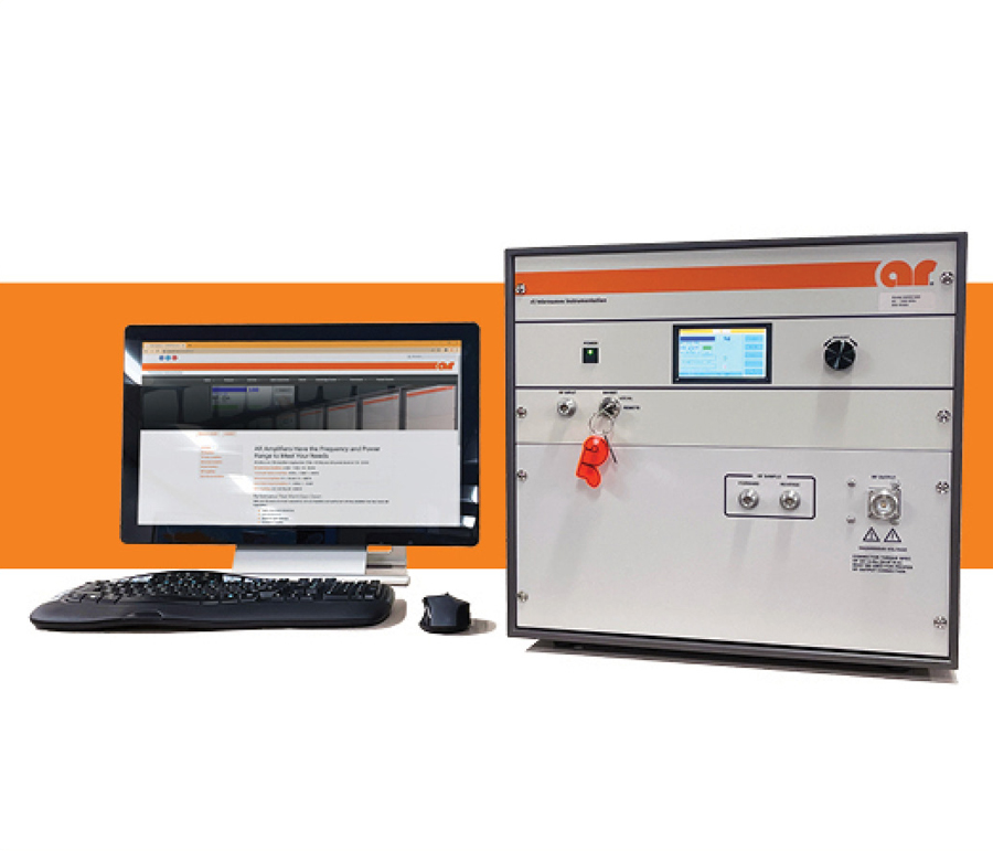
- Determine the frequency range of operation needed, sometimes more than one amplifier is required.
- Determine if you need a Pulse or CW type of amplifier. Example: HIRF EMC applications require high power pulse amplifiers..
- Determine the minimum acceptable linear or saturated power needed from the amplifier. Harmonics should be considered based on the frequency range. Example: As you go up in frequency antenna gain improves so a lower power amplifier may be acceptable but the higher gain of the antenna may affect the Harmonic Level.
- Assess the system losses between the amplifier and the antenna/DUT. Example: If the test setup has 6dB of losses then the Amplifier power needs to be 6dBm higher.
- Some modulations if required for the test application, would require a higher power amplifier. Example: When performing an 80% AM modulation test the amplifier needs to have 5.1dBm of margin to accommodate the peak.
- Antennas, cables, DUTs, and rooms have cumulative VSWR, it is best to allocate for some power margin. Example: working into a 2:1 requires 12% more forward power.
- Consider the application, is this a single test or will it be used repetitively?
- Consider your desired RF connection types and locations to be optimal for your application.
- Consider if automation will be used so the appropriate remote capability is included.

Exodus
the Rest
industry firsts
with our frequency
& power capabilities

1.0-18.0GHz, 100W, 200W, 300W, 500W…
1.0-40.0GHz, as well and for the 18.0-40.0GHz range 40W, 100W, 200W
can do this anywhere!!!
702-534-6564 • www.exoduscomm.com • sales@exoduscomm.com
hose involved in compliance engineering are often required to read many standards and comprehend them so they can guide others. Although informative, many of these same standards are not very exciting to read, are often confusing, and seem like they contain conflicting requirements. Most are not meant to be read like a novel but are better suited to reading small sub-sections at a time. There are exceptions to the rule, and the following briefly describes an exceptionally well-written standard that breaks the typical mold.
Due to advances in technology over the past 40 or so years, it was not possible to maintain the intent of the original standard as a standardized test procedure for antennas. Therefore, the committee reclassified IEEE Std 149-1977 as a recommended practice, intending to have it function instead as a guideline for obtaining the highest quality measurements without prescribing an exact method. The new recommended practice, however, does preserve many familiar areas covering antenna measurements and range evaluations but depicts them using the latest state-of-the-art industry best-practice methods and contemporary tools.
s compliance engineers and technicians involved in new product development, much of our time spent developing shielding (or consulting with others who do) is mostly devoted to developing shielding that is suitable for high frequency (HF) signals (those signals that have frequencies greater than 100 kHz). In case you need a refresher on how this type of shielding is accomplished, reference 1 covers this topic at a high level.
Occasionally, we are asked to help develop shielding that is effective for near-field low frequency (LF) magnetic fields. Perhaps in a situation where some regulatory agency has imposed limits on LF magnetic field emissions of our product and we are forced to comply? In this situation, we find ourselves caught a bit off guard and may not know what to do since the shielding design techniques we know well (those used for shielding HF signals) will not work for LF magnetic fields. If you find yourself in this situation and are unsure what it takes to develop shielding that is effective for LF magnetic fields, please read on.
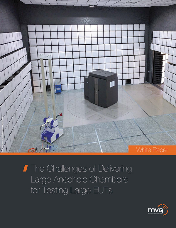
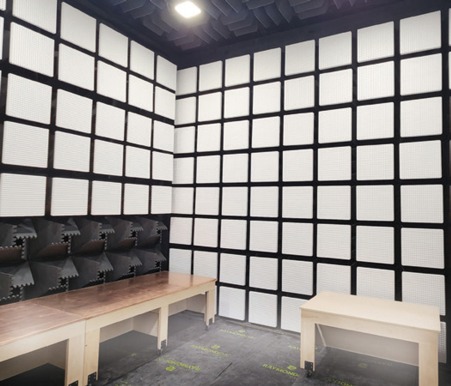
- Define your application and define the test types you need to perform to identify the correct type of chamber and test system to meet your specific requirements.
- Specify the device(s) to be tested: Handsets, base stations, vehicle radar and other devices are vastly different and testing them in the same chamber and test system might not be possible. Specifying the device(s) to be tested and the test volume will aid in identifying the correct chamber type and test system for your specific application.
- Understand how to specify accuracy. Specifying accuracy for FR1 applications is very different from FR2 applications. Standards like CTIA, 3GPP, and ETSI provide direction on how to specify the necessary measurement accuracy.
- Verify your software can perform the required measurements and determine how that software may impact your productivity.
- Consider chamber, system and software maintenance support. Chambers and systems require a periodic validation and maintenance is fundamental to assuring minimal interruptions for your everyday operations. Downtime can have a significant impact on productivity and the bottom line.
- Consider future technologies and the assets you may need to be able to support future testing requirements. Ensure that the selected software supports current instrumentation and test requirements, and can expand when your test requirements evolve in the future, ensuring the longevity of the initial investment. Current requirements defined by standards can change quickly and making sure that your test solution can adapt provides your organization a sense of security.

- Since chamber selection is primarily driven by testing requirements, clearly define applicable test standards, operating frequency range, and whether the chamber will be multi-function.
- Consider the shape, size, weight, type, and heat generation of devices intended to be tested. Ensure that the chamber dimensions can comfortably accommodate the devices under test.
- If the chamber will be installed in an existing facility, choose a layout that conforms to space limitations and constraints imposed by the parent room.
- A chamber manufacturer can help navigate local permitting requirements, fire suppression systems, seismic approvals, structural supports, emergency features, safety systems, and design for extreme environmental conditions.
- The type, size, placement, and number of RF shielding doors should be decided based on frequency of personnel access and the expected movement of devices under test.
- Explore options for chamber accessories and test equipment including turntables, antenna masts, test tables, crane or hoisting systems, shielded cameras, ramps, and more.
- Assess connections to the parent building for electrical, HVAC, and fire suppression systems.
- Determine if a control room, raised floor, or other custom configuration is required for cable management.
- A modular chamber design that allows for customization, expansion, upgrades, or potential relocation, can help expand test capabilities and adapt to future needs.
- To extend the usable lifetime of the chamber and to ensure performance, regular preventative maintenance and chamber validation testing are essential.

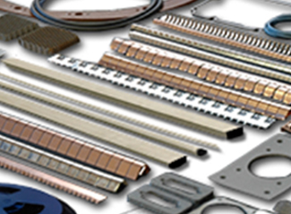
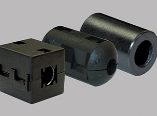
few basic system components are frequently used to mitigate or suppress electromagnetic interference (EMI) in devices. As engineers and technicians involved in compliance engineering, it is important to know what these components are, what they do, how they’re most effective, and when they’re ineffective. You will often be involved in reducing EMI or Electrostatic Discharge (ESD) to pass compliance tests or simply need to make your product more robust to EMI/ESD. So, it would be wise to know a little about systems components used to reduce EMI. In alphabetical order, some of these components are:
- Capacitors
- Common Mode Chokes
- Diodes
- EMI Filters
- Ferrites
- Inductors
- Resistors
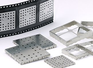
any years ago, the author experimented on a metal enclosure of one of his company’s main products. The experiment involved placing an electric field probe inside the empty metal enclosure (no electronics inside) and applying 10 V/m using the IEC 61000-4-3 radiated RF immunity test system. The E-field levels measured by the probe were recorded over the frequency range of 80 to 1000 MHz. The probe was placed in several locations within the box. The results were supersizing, to say the least. One would expect the 10V/m signal to be highly attenuated by shielding effectiveness of the metal box of 40 dB or so; however, over certain frequencies, the signal was amplified! I recall seeing levels as high as 60 V/m or more inside this empty metal box. The most likely culprit of this unexpected result was probably due to cavity resonance.


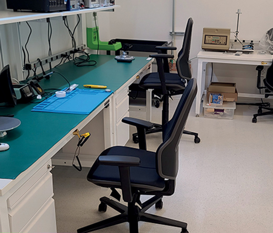
When establishing an ESD-control system, always consider the following:
- Site assessment: Consider the sensitivity of components: use or non-use of ESD footwear; use/maintenance of seating, carts and floors; component integration.
- Footwear: ESD footwear forms an electrical bond with the ESD floor. ANSI/ESD S20.20 mandates the use of ESD footwear.
- ESD floor: The floor should always be tested for resistance and body voltage, and measure in the proper, industry-standard ranges for the application.
- Seating: Standing from a chair can generate significant static charges. ESD chairs dissipate the static people generate while seated and transport it to the floor and then to an earth ground.
- Grounding: Always check electrical contact with the floor. The conductive granules in some ESD floors may not make reliable contact with drag chains or castors.
- Redundancy and Grounding Paths: Test all ground connections to ensure they are intact.
- Integration: Each item must work in conjunction with all grounding measures and equipment.
- Awareness: Raise awareness of the purpose, usage and limitations of the ESD system, as well as of proper procedures and protocols.
- Compliance with ESD Standards: All grounded components should comply with relevant industry standards, such as ANSI/ESD S20.20 or IEC 61340‑5-1.
- Maintenance and Testing: Routinely inspect the condition of ground cords; verify the conductivity of seats and flooring; and address any issues promptly.

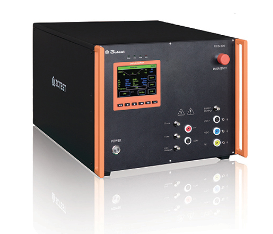
he most common system-level method for electrostatic discharge (ESD) testing is what is sometimes referred to as the Hand Metal Model (HMM). This ESD testing method is performed per familiar standards such as IEC 61000-4-2, DO-160, MIL-STD-461 CS118, etc. We’ve previously covered other important points about the HMM method of ESD testing under the Product Insight’s category of In Compliance Magazine (See References 1 through 4 for details).
To provide further in-depth coverage of ESD testing methods, in this article, we look at another type of ESD testing based on the “Human Body Model” (HBM) method of ESD testing.

apacitors are used to filter out system noise to obtain the best EMC performance of a product, usually in bypass or decoupling scenarios. Many common capacitor technologies are used in these filtering applications, each exhibiting unique behaviors. Although understanding each capacitor type and behavior is daunting and difficult to memorize, it is prudent that every aspiring engineer and technician involved in design for EMC at least have a rudimentary understanding of what capacitor technologies are available. This short article intends to provide a primer for you to obtain additional knowledge as required by your unique circumstance and filtering requirements.
- Aluminum electrolytic
- Aluminum polymer
- Aluminum hybrid polymer
- Ceramic
- Plastic Film
- Mica
- MLCC
- Tantalum
nyone involved in the development of high-tech products should understand the consequences brought about by such items as component die-shrinks, lower voltage levels, faster rise/fall times, higher switching speeds, etc. These elements often mean more diligence and thoughtful attention to detail is required in laying out circuits today, more so than they ever have been in the past. These extra precautions are required to ensure proper circuit functionality and to meet timing, signal integrity and electromagnetic compatibility (EMC) requirements, to name a few.
Have you ever done everything you could to ensure that your design met all the necessary requirements before building an actual prototype, only to discover issues once you had the functioning hardware in hand? These issues could be related to functionality, signal integrity, EMC, or something else, and they could prevent your design from being released to production on time. If you don’t have a way to quickly troubleshoot these high-speed or high frequency issues within your design, you will be left with guessing what could be wrong. You may make changes based on engineering judgment and intuition, but you will likely have to repeat the process until a solution is found.
It’s easy to see that the trial-and-error approach of guessing what is wrong with your design is flawed and consumes a lot of time and resources. Furthermore, upper management may not be pleased if a solution isn’t found quickly enough. To escape this seemingly endless and frustrating cycle, you must be resourceful and use high frequency probing and measurement techniques to gather actual measured data. You’ll need certain knowledge and tools to develop this skill, which will be discussed shortly. But first, let me clarify what I mean when I say “be scrappy.”

No Problem – Use Python’s SciPy Module Instead
pectrum analyzers are used to capture the amplitudes and frequencies of time-domain signals, plotting these signals horizontally across a display, with lower frequencies on the left and higher frequencies on the right. Spectrum analyzers operate on the principle of the Fast-Fourier Transform (FFT) algorithm and have many important uses in compliance engineering, including noise analysis of measurement systems.
A measurement system could be a circuit that measures voltage or current using an analog-to-digital converter (ADC) that outputs ADC counts that represent the time-domain signal captured by the system. In such systems, it is important to determine how much unwanted noise is in the system as this noise could negatively impact the accuracy of the measurement system because the unwanted noise could mask the wanted signal.
A spectrum analyzer is a useful tool for hunting down unwanted noise in a measurement system. But what if, for whatever reason, you didn’t have a spectrum analyzer at your disposal? Not determining the noise characteristics of your system is not an option, so what else could you do to determine how much noise was in your measurement system? Well, if you had a way to capture the output of the ADC, for instance, then you could use the Python programming language, and its SciPy FFT module to analyze this data. Since it’s a little tricky getting the SciPy FFT function to give you the correct output (you can’t just plop your measurement data into the FFT module and expect it to work correctly), you’ll want to have a rudimentary understanding of how to use Python as a pseudo-spectrum analyzer. If you’re interested in learning how to do this, read on. The following is provided to get you started using the SciPy FFT function as a replacement for a spectrum analyzer.

EC 61000-4-6 is titled “Electromagnetic compatibility (EMC) – Part 4-6: Testing and measurement techniques – Immunity to conducted disturbances induced by radio-frequency fields.” This “conducted RF immunity” standard covers the conducted immunity requirements of electrical and electronic equipment to electromagnetic disturbances from intended radio-frequency (RF) transmitters in the frequency range 150 kHz up to 80 MHz.
As one can imagine, the coupling (C) part of the CDN is used to couple energy into the equipment under test (EUT). In contrast, the decoupling (D) part of the CDN is used to prevent unwanted injected test signals from disrupting any auxiliary equipment used to provide functional signals to the EUT.

- Do you know what standards are required?
- Do you own a copy of the standards?
- Do your design engineers know the standards and how to comply?
Answer “NO” to any of these questions? You need to contact CertifiGroup. We will help you all the way! That includes performing the entire certification process in our 25,000 sq. ft. test lab. On time, on budget! Contact us today at 800-422-1651.
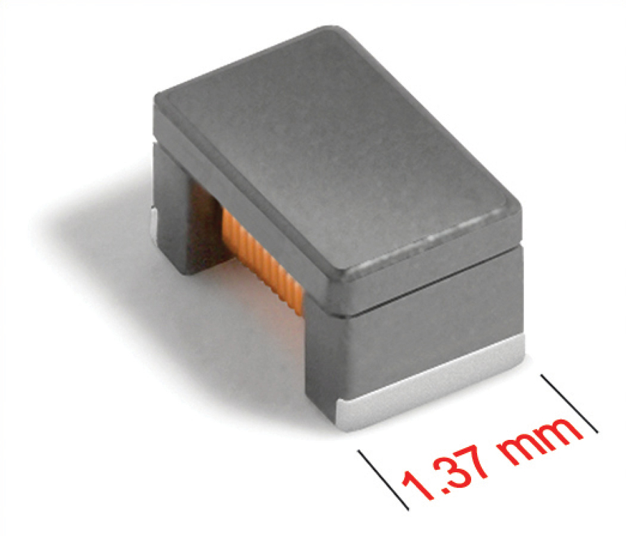


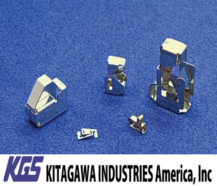
- Effective for suppressing emission and immunity reduction
- All EMC mitigation can be done at the board-level
- Space-saving and robust design
- Easy to incorporate even where screws are included
- Tape-and-reel design allows for use with automated pick-and-place machine to increase efficiency and reduce manual labor


We encourage you to learn more about their products and services.
-
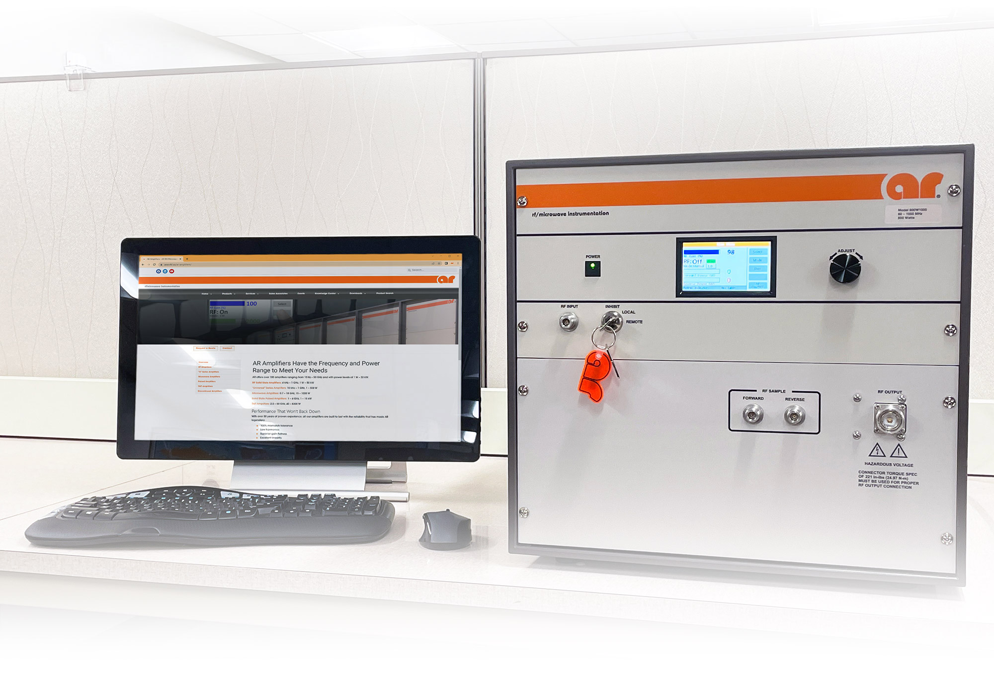
AR RF/Microwave Instrumentation

160 School House Road
Souderton, PA
(215) 723-8181
https://www.arworld.us -
ETS-Lindgren

1301 Arrow Point Drive
Cedar Park, TX
(512) 531-6400
https://www.ets-lindgren.com -
Leader Tech Inc.

12420 Race Track Road
Tampa, FL
(813) 855-6921
https://www.leadertechinc.com -
Raymond EMC

5185 Dolman Ridge Road
Ottawa, Ontario, Canada
(800) 362-1495
https://raymondemc.com
-
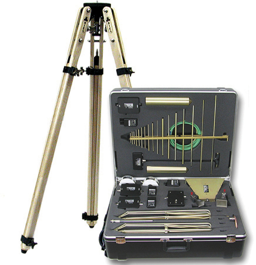
A.H. Systems, Inc.

9710 Cozycraft Avenue
Chatsworth, CA
(818) 998-0223
https://www.ahsystems.com -
AR RF/Microwave Instrumentation
160 School House Road
Souderton, PA
(215) 723-8181
https://www.arworld.us -
Exodus Advanced Communications

3674 East Sunset Road
Las Vegas, NV
(702) 534-6564
https://www.exoduscomm.com -
ETS-Lindgren
1301 Arrow Point Drive
Cedar Park, TX
(512) 531-6400
https://www.ets-lindgren.com -
HV Technologies, Inc.

8526 Virginia Meadows Drive
Manassas, VA
(703) 365-2330
https://www.hvtechnologies.com -
Rohde & Schwarz USA

6821 Benjamin Franklin Drive
Columbia, MD
(888) TEST-RSA (837-8772)
https://www.rohde-schwarz.com
-
A.H. Systems, Inc.
9710 Cozycraft Avenue
Chatsworth, CA
(818) 998-0223
https://www.ahsystems.com -
ETS-Lindgren
1301 Arrow Point Drive
Cedar Park, TX
(512) 531-6400
https://www.ets-lindgren.com -
HV Technologies, Inc.
8526 Virginia Meadows Drive
Manassas, VA
(703) 365-2330
https://www.hvtechnologies.com
-
Global Validity

8601 Six Forks Road, Suite 400
Raleigh, NC
(877) 464-6753
https://globalvalidity.com
-
ETS-Lindgren
1301 Arrow Point Drive
Cedar Park, TX
(512) 531-6400
https://www.ets-lindgren.com -
Raymond EMC
5185 Dolman Ridge Road
Ottawa, Ontario, Canada
(800) 362-1495
https://raymondemc.com
-
Coilcraft

1102 Silver Lake Road
Cary, IL
(847) 639-6400
http://www.coilcraft.com -
ETS-Lindgren
1301 Arrow Point Drive
Cedar Park, TX
(512) 531-6400
https://www.ets-lindgren.com -
Kikusui America

3625 Del Amo Boulevard
Torrance CA
(310) 214-0000
https://www.kikusuiamerica.com -
Kitagawa Industries America, Inc.

2860 Zanker Road
San Jose, CA
(408) 971-2055
https://kgs-ind.com -
Leader Tech Inc.
12420 Race Track Road
Tampa, FL
(813) 855-6921
https://www.leadertechinc.com -
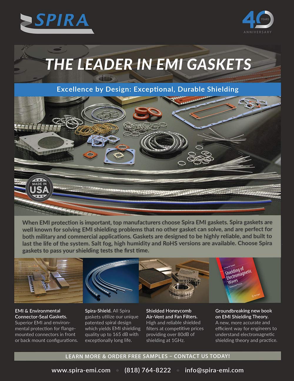
Spira Manufacturing Corporation

650 Jessie Street
San Fernando, CA
(888) 98-SPIRA (77472)
https://www.spira-emi.com -
Würth Elektronik

Max-Eyth-Strasse 1, Waldenburg Baden‑Württemberg, Germany
49 7942 945 – 0
https://www.we-online.com
-
AR RF/Microwave Instrumentation
160 School House Road
Souderton, PA
(215) 723-8181
https://www.arworld.us -
Kitagawa Industries America, Inc.
2860 Zanker Road
San Jose, CA
(408) 971-2055
https://kgs-ind.com -
Leader Tech Inc.
12420 Race Track Road
Tampa, FL
(813) 855-6921
https://www.leadertechinc.com -
Spira Manufacturing Corporation
650 Jessie Street
San Fernando, CA
(888) 98-SPIRA (77472)
https://www.spira-emi.com -
Würth Elektronik
Max-Eyth-Strasse 1, Waldenburg Baden‑Württemberg, Germany
49 7942 945 – 0
https://www.we-online.com
-
SelecTech

33 Wales Avenue, Suite F
Avon, MA
(877) 738-4537
https://www.staticstop.com -
staticWorx, Inc.

372 Hurricane Lane
Williston, VT
(617) 923-2000
https://staticworx.com
-
HV Technologies, Inc.
8526 Virginia Meadows Drive
Manassas, VA
(703) 365-2330
https://www.hvtechnologies.com -
Kikusui America
3625 Del Amo Boulevard
Torrance CA
(310) 214-0000
https://www.kikusuiamerica.com -
Suzhou 3ctest Electronic Co, Ltd.

Anda Technology Park Jinshan Road, Suzhou, China
86-512-6807 7192
https://www.3c-test.com
-
Coilcraft
1102 Silver Lake Road
Cary, IL
(847) 639-6400
http://www.coilcraft.com -
Kitagawa Industries America, Inc.
2860 Zanker Road
San Jose, CA
(408) 971-2055
https://kgs-ind.com -
Leader Tech Inc.
12420 Race Track Road
Tampa, FL
(813) 855-6921
https://www.leadertechinc.com -
Spira Manufacturing Corporation
650 Jessie Street
San Fernando, CA
(888) 98-SPIRA (77472)
https://www.spira-emi.com -
Würth Elektronik
Max-Eyth-Strasse 1, Waldenburg Baden‑Württemberg, Germany
49 7942 945 – 0
https://www.we-online.com
-
Rohde & Schwarz USA
6821 Benjamin Franklin Drive
Columbia, MD
(888) TEST-RSA (837-8772)
https://www.rohde-schwarz.com
-
Rohde & Schwarz USA
6821 Benjamin Franklin Drive
Columbia, MD
(888) TEST-RSA (837-8772)
https://www.rohde-schwarz.com
-
Absolute EMC Llc.

14126 Wood Rock Way
Centreville, VA 20121
(703) 774-7505
https://absolute-emc.com -
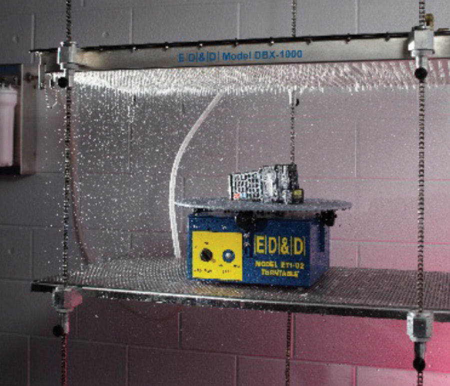
E. D. & D., Inc.

901 Sheldon Drive
Cary, NC
(800) 806-6236
http://www.productsafet.com -
Kikusui America
3625 Del Amo Boulevard
Torrance CA
(310) 214-0000
https://www.kikusuiamerica.com
-
Absolute EMC Llc.
14126 Wood Rock Way
Centreville, VA 20121
(703) 774-7505
https://absolute-emc.com -
Lightning EMC

300 Hylan Drive #170
Rochester, NY
tel: (585) 552-2080
https://www.lightningemc.com -
Ross Engineering Corporation

540 Westchester Drive
Campbell, CA
(408) 377-4621
https://www.rossengineeringcorp.com
-
Advanced Test Equipment Rentals

10401 Roselle Street
San Diego, CA
(800) 404-2832
https://www.atecorp.com
-
Certifigroup

901 Sheldon Drive, Cary, NC
(800) 422-1651
https://www.certifigroup.com -
F2 Labs

26501 Ridge Rd.
Damascus, MD
(301) 253-4500
https://f2labs.com
his is the first article of a three-article series devoted to the correlation between the insertion loss and input impedance of passive EMC filters. In this article, we focus on LC and CL filters. Based on the analysis, simulation, and measurement results, it has been observed that the frequencies where the insertion losses of the filters are equal are also the frequencies where the input impedances are equal. These frequencies define the regions where one filter configuration outperforms the other (with respect to the insertion loss). To determine these regions analytically, we compare the input impedances of the two filters. Subsequent articles will focus on π and T filters and cascaded LC and CL configurations.
CDE Modeling Using Star-Tree Impedance Networks for USB2 Cable
revious studies of cable discharge events (CDE) have often used oversimplified models of the cable, such as a single 50Ω transmission line. This is not bad for an initial investigation, but the next level of detail is not difficult to capture for some familiar data cables. This work focuses on a star-tree impedance model for the 5-node USB2 cable and outlines a methodology for treating other cables, such as USB3 and HDMI.
The Cable Discharge Event (CDE) is an important ESD topic of continuing interest [1,2]. But to quantify CDE and observations, a simple and accurate electrical model of the cable itself is needed for future studies of on-silicon ESD protection optimizing for cost performance and improved reliability. Industry specifications leave much latitude at the expense of clarity. After considerable study and to promote understanding, we devised simple, lucid models for USB2, USB3, and HDMI cables based on star and tree networks [3]. These utilize measurements of capacitance and propagation velocity (and therefore inductance and impedance) that give models with reduced parameter count and agree well with the experiment. In this brief article, we model the five-node USB2 cable (Figure 1) and plan to cover similar models for USB3 and HDMI in the 2024 EOS/ESD Symposium.
n our “On Your Mark” columns, we often discuss the importance of American National Standards Institute (ANSI) Z535. This family of U.S. standards was created to enhance safety communication and promote consistent hazard recognition and understanding – making it critical for manufacturers and workplaces across the country. The six (soon to be seven) Z535 standards create a guide for the design, application, and use of signs, colors, and symbols intended to identify and warn against hazards and for other accident prevention purposes. Our theme of exploring one of these standards in depth continues, this month focusing on ANSI Z535.3 – Criteria for Safety Symbols.
The ANSI Z535.3 standard focuses solely on guidelines for the design and use of safety symbols. It establishes criteria for creating symbols that effectively convey safety information across different languages and cultures. The goal: to promote the adoption of effective safety symbols for safety communication and to supply a procedure to do just that.

The paper machine process requires precise control of the paper sheet tension as it progresses through the machine. On Caledonian Paper’s paper machine this is achieved by controlling 23 separate DC variable speed drives, which are inherently vulnerable to voltage disturbances because of problems with the control of thyristor firing…
The FCC’s Kansas City office received a complaint that the Search and Research Satellite Aided Tracking (SARSAT) system was experiencing interference from an unknown source. SARSAT is used by search-and-rescue teams to locate the radio beacon transmitters of crashed aircraft and distressed ships. Using mobile direction-finding gear, the FCC tracked the interference to a (presumably malfunctioning!) video display unit at a Wendy’s restaurant…
Trigano et al, in [5] report an electrocardiogram recorded during 1800 MHz cellular phone ringing with high amplitude and high-frequency artefacts that appears 3 seconds before the first ringing tone and that persisted until end of ringing. As consequence of these facts many hospitals have prohibited the use of cellular phones in some areas…
In this issue of Mayo Clinic Proceedings, 3 articles bring the issue of exposure to electrical transmissions and patient safety to the forefront. Tri et al1 report on their investigation of possible cell telephone interference with medical equipment in a hospital setting. Gimbel and Cox2 provide a report of 2 patients with implantable cardioverter defibrillators (ICD) who had adverse interactions with electromagnetic…


View Index
45th EOS/ESD Symposium and Exhibits
October 3
IEEE EMC Milwaukee Seminar: Printed Circuit Board Design for EMC Compliance
October 3-6 and 17-20
Applying Practical EMI Design & Troubleshooting Techniques
Advanced Printed Circuit Board Design for EMC + SI
Mechanical Design for EMC
The Battery Show India
October 8-13
45th Annual Meeting and Symposium of the Antenna Measurement Techniques Association (AMTA) Advanced Printed Circuit Board Design for EMC + SI
October 17
San Diego Test Equipment Symposium
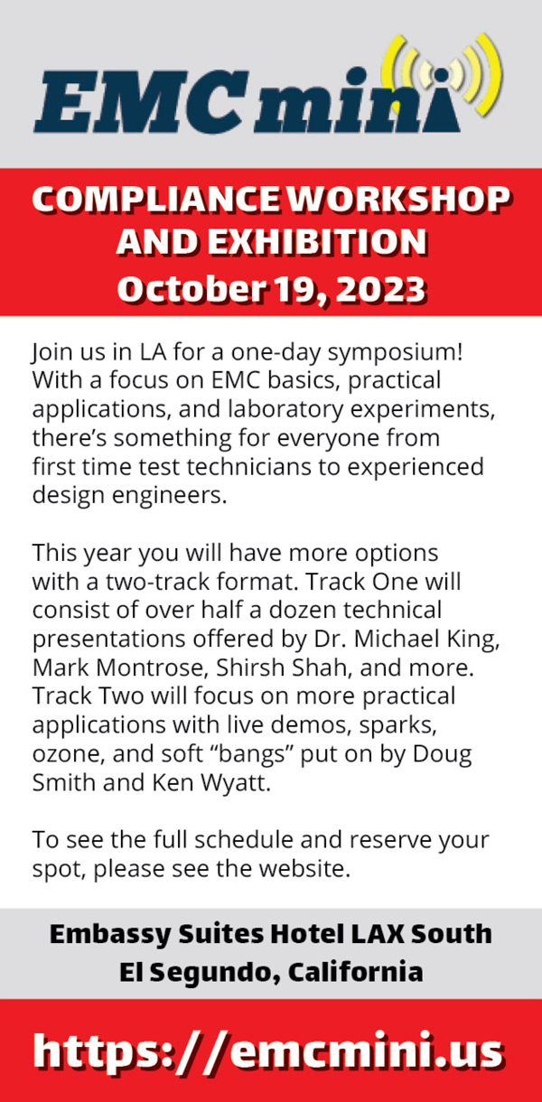
October 19
EMC Mini Compliance Workshop and Exhibition
Fundamentals of Random Vibration and Shock Testing Training
December 4-7
Military Standard 810 (MIL‑STD-810) Test Training